MrDEB
Well-Known Member
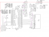
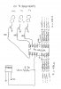
Need to construct this unit but not real sure of the 4.7K R! resistor.
Do I need one for each probe (4 separate probes)
I looked at this guide but still have questions
**broken link removed**
The LEDs are green and red arrays (4 green 4 red)
my plan is to have one green and one red per probe as an indicator. If temperature drops below set temp then green LED flashes. If higher than set temp then Red led flashes.
Need to include a mont pushbutton to vied temps when desired (no need to have display running 24/7
If and when I get this thing running I hope to add a past history feature where the temps can be displayed to indicate adverage temp over a 24 hour period or more say 7 days.
Need to etch a PCboard so any errors or suggestions in schematic would be appreciated.