+ Reply to Thread
Results 1 to 4 of 4

Thread: Can passive filter magnify signals?

  1. #1
    xiongyw Newbie
    Join Date
    Jun 2009
    Location
    Beijing, PRC
    Posts
    28

    Can passive filter magnify signals?

    Hi,

    I am studying basic electronics in spare time.

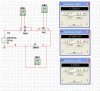
    Enclosed is a simple RLC circuit I made by MultiSim (the capacitance and inductance values are chosen intentively small and big). It seems the amplitudes (regardless the phase shift here) of the voltage drops on C and L can be very large, as compared to that of the input voltage. That means, if this circuit is used as a filter network, then we can get magnified signal from C or L. That means we get both filtering and amplification functionality from the passive network. My question is, is this correct, or if this kind of configratuion often used in pracitical circuits? If not, why?

    Btw, yes, I am aware of that, if only C or L is used with R, the amplitude of the voltage drop on either of them (R and C or L) can not be bigger than the amplitude of the input voltage (i.e., according to side length relationship of right-angled triangles).


    Thanks,
    /bruin
    Attached Images


  2. #2
    MikeMl Excellent MikeMl Excellent MikeMl Excellent MikeMl Excellent MikeMl Excellent MikeMl Excellent MikeMl Excellent
    Join Date
    Mar 2009
    Location
    Utah
    Posts
    2,529

    The magnitude of the voltage across the inductor and capacitor can be larger than the input voltage only because they have opposite phases. AC voltages are vectors, meaning they have both magitude and phase, so a series RLC circuit still satisfies Kirchoff's voltage law (sum of vector voltages around the loop = zero). Practical circuit, tuned stages in a radio utilize the voltage step-up across a high Q LC circuit.
    Last edited by MikeMl; 30th June 2009 at 07:09 AM.

  3. #3
    xiongyw Newbie
    Join Date
    Jun 2009
    Location
    Beijing, PRC
    Posts
    28

    Quote Originally Posted by MikeMl View Post
    The magnitude of the voltage across the inductor and capacitor can be larger than the input voltage only because they have opposite phases. AC voltages are vectors, meaning they have both magitude and phase, so a series RLC circuit still satisfies Kirchoff's voltage law (sum of vector voltages around the loop = zero). Practical circuit, tuned stages in a radio utilize the voltage step-up across a high Q LC circuit.
    Thanks for the information, Mike!

    I had this question is because I have a (wrong) impression that the gain in amplitude of a filter is always less than 0dB. I will check out the tune stage circuits used in radio.

    Actually this question emerged when I was trying to summarize what I learnt so far (as the attached picture). I was trying to answer a question raised during the process (item in red): why using L and C together in a series circuit when they voltage drops cancel each other? Can you also please give some hints or clarify a bit on that? It will also be very helpful if you can review the other items to see if there are faults or missed points.


    Thanks again,
    /bruin
    Attached Images
    Last edited by xiongyw; 30th June 2009 at 07:56 AM.

  4. #4
    Tesla23 Newbie
    Join Date
    Jul 2008
    Location
    Australia
    Posts
    98

    Quote Originally Posted by xiongyw View Post
    I had this question is because I have a (wrong) impression that the gain in amplitude of a filter is always less than 0dB.
    The power gain of a passive circuit is never greater than 0dB.

    The voltage or current gain may be greater than 0dB. Think of a simple transformer as an example.

+ Reply to Thread

Similar Threads

  1. Basic knowledge in Passive Filter Design
    By qq8807 in forum Electronic Projects Design/Ideas/Reviews
    Replies: 6
    Latest: 2nd December 2008, 03:42 AM
  2. how do I magnify a voltages in a certain range from a sensor?
    By ghsrocketman in forum Electronic Projects Design/Ideas/Reviews
    Replies: 3
    Latest: 24th July 2007, 08:38 AM
  3. passive crossovers
    By Gaston in forum General Electronics Chat
    Replies: 9
    Latest: 14th February 2007, 01:57 PM
  4. Filter ,a band pass filter working around 20khz
    By santosh_iitm2002 in forum Electronic Projects Design/Ideas/Reviews
    Replies: 3
    Latest: 22nd September 2004, 05:31 PM
  5. Bandpass Filter for a Vocoder?high order filter??? advice!!!
    By damenace in forum Electronic Projects Design/Ideas/Reviews
    Replies: 2
    Latest: 27th June 2003, 09:59 AM

Tags for this Thread