Hey Guys,
Glad I found this forum. I know very little about electronics and am just a hobbyist. Anyhow I do engine swaps in cars and then build electronic tach converter boxes to allow the factory tach in the dash to work correctly.
What I currently have is a v8 engine going into a v6 car so a v6 tach in the dash.
Anyhow I built a simple decade counter which drops pulses and the v6 tach works perfectly. BUT..., you knew there was a "but", only when the tach signal is fed by a very clean signal source such as an after market ignition box that has a dedicated 12 volt square wave tach signal output.
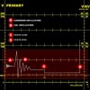
The problem is the majority of swaps don't use this ignition box but instead take their tach signal source from the 12v side of the ignition coil. That signal is very noisy though and the tach needles just jumps about crazy and does not work.
If you go purchase an after market tach, that is the same spot they take their signal source, from the 12v side of the ignition coil (not the HV side of course).
So... I think what I need is some sort of line filter to clean up the signal before going into my somewhat simple decade counter to drop pulses. My problem is I have no clue how to build one of these filters, can anyone help?
Thanks so much for any assistance.
Malcolm
Glad I found this forum. I know very little about electronics and am just a hobbyist. Anyhow I do engine swaps in cars and then build electronic tach converter boxes to allow the factory tach in the dash to work correctly.
What I currently have is a v8 engine going into a v6 car so a v6 tach in the dash.
Anyhow I built a simple decade counter which drops pulses and the v6 tach works perfectly. BUT..., you knew there was a "but", only when the tach signal is fed by a very clean signal source such as an after market ignition box that has a dedicated 12 volt square wave tach signal output.
The problem is the majority of swaps don't use this ignition box but instead take their tach signal source from the 12v side of the ignition coil. That signal is very noisy though and the tach needles just jumps about crazy and does not work.
If you go purchase an after market tach, that is the same spot they take their signal source, from the 12v side of the ignition coil (not the HV side of course).
So... I think what I need is some sort of line filter to clean up the signal before going into my somewhat simple decade counter to drop pulses. My problem is I have no clue how to build one of these filters, can anyone help?
Thanks so much for any assistance.
Malcolm
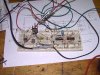
") You especially don't want to see my PCB designs LOL
You especially don't want to see my PCB designs LOL in the signal levels.