Continue to Site

Welcome to our site!

Electro Tech is an online community (with over 170,000 members) who enjoy talking about and building electronic circuits, projects and gadgets. To participate you need to register. Registration is free. Click here to register now.

  • Welcome to our site! Electro Tech is an online community (with over 170,000 members) who enjoy talking about and building electronic circuits, projects and gadgets. To participate you need to register. Registration is free. Click here to register now.

tachometer signal input

Status
Not open for further replies.

schuman_7

New Member
hie there...
i know there a lot of threads on this forum about tachometers and all....my problem is however...hehe.....is that i have already build the circuit and its ready to test....but i don't exactly know where to connect the input signal to the engine....
hope anyone out there who have build a tachometer before help me on this.....
btw....my circuit is build on a LM2917 as a freq to voltage converter and the led's are drived by a LM3914 driver....
 
A whole lot depends on what you're putting it on. The tachs I 've delt with are connected to the neg side of ignition coil. There they monitor the opening and closing of the ignition points and devide by the number of cylinders..On the some of the newer vehicles there is a tach terminal on the ignition module that corresponds with the electronic trigger for the coil.
 
It all depends on your motor ignition configuration, coil system etc...

Normally, you would connect to the LT (low tention) side of the coil, for a conventional (points) ignition system, this is the wire that connects to the points inside the distrubutor and is 1 pulse per clylinder per RPM.


For distrubutor-less (DIS) engines, the plugs are fired in pairs (only one spark is used, the other in the pair is waisted) so there are 2 LT connections for a 4-clylinder motor, only one is required -- you will get 2 pulses per revoltion.


If your car is "coil on plug", then the signal that you need to find will be low-level and direct from the ECU, there will be one wire per clylinder, you only need to connect to one of the wires, you will get 1 pulse per rev.

You can also gain access to the signal from the ECU (for modern cars).
 
I have a similar kind of problem - built the circuit and it works, but I'm not 100% sure why :)

I've got an old suby with (I think) an electronic distributor.

I built the circuit as for a "points" style ignition, because I don't really understand what the difference between that, and the one I have is - shouldn't they all just swing the coil supply ?

As described in the 2917 datasheet, there's a diode on the negative comparator input (pin 12), which holds it at 0.6V.

The input then gets 1/3 knocked off by a voltage divider, and is fed into pin 1 with a 0.02uF cap to ground.

I measured the input at pin 1 about 8V DC, and 3 V AC on my DMM (not sure if the AC is RMS or not). This was not triggering the tach.

I added a diode forward biased towards pin 1 (ie. current can flow from coil to pin 1) and bingo, it worked. I'm kind of curious why ...

I'm just not sure how to make sense of the readings I was seeing, and why the diode fixed it.
 
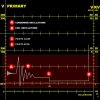
This is what you get on the negative coil terminal. The spike is over 100 volts. Electronic ignition is similar. Complete explanation at **broken link removed**
 

Attachments

  • Points primary.jpg
    Points primary.jpg
    43 KB · Views: 899
Thanks, a couple of questions about that graph though - which scale should I be reading ? At point C, what voltage does the coil drop from and to ? It looks like closing the points takes it low, or am I reading the wrong scale ?
 
The points ground the coil so the line between C and D is at ground. Use the primary scale on the left. It doesn’t say but I would think they are using the 0 to 200 volt scale.
So the spike would be about 115 volts. The coil oscillations do go below ground.
 
If I want to make a signal for a tach that is programed for a 8 cylinder engine with a points style ignition I just need to supply negative and break the current flow 4 times per revolution of the shaft? Sorry about the incorrect terminology, I am a beginner at this stuff and don't know all the correct words yet.
 
They are using the KV scale on the right of the screen.
D would be the actual firing of the cylinder when the points open and
C would be points closed for charging the coil.
 
Status
Not open for further replies.

Latest threads

New Articles From Microcontroller Tips

Back
Top