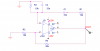
Electronic Projects, forums and more.

Go Back   Electronic Circuits Projects Diagrams Free > Electronics Forums > Electronic Projects Design/Ideas/Reviews


Electronic Projects Design/Ideas/Reviews Are you building an electronic project or want to? Maybe you need some assistance? Come and submit your electronic questions here and let our experienced members find a solution.

Reply
 
Tools
Old 19th October 2009, 02:19 PM   #31
Default

The diode clipper clips the signal the same as the same circuit in a guitar fuzz effects circuit. But if there is a resistor in series with the diodes then the clipping distortion is reduced.
__________________
Uncle $crooge
audioguru is offline  
Old 19th October 2009, 04:44 PM   #32
Default

Quote:
It seems that you don't know how to properly "set" the simulation.
Here you have two examples:
thank you for your reply Jony130 as well as helping teach me simulate. if you are referring to the previous post where i had the gain set at 3 for the circuit without amp stab, i purposely set it to those parameters to have a closer view..under normal parameters, i get an overall flat line..which is correctly represented when the gain is exactly 3 returning no oscillations. am i having the correct concept? i stand corrected..other than that the parameters on my time transient analysis are identical to yours.=)

referring to your second circuit with the diode bridge. i would like to ask why resistances of R3,R4 and R6 are assigned those values of 10k, 4.7k and 2.35k (VR set to 0.5) respectively.From the gain formula 1+R2/R1..after the diodes get turned on and R5 is bypassed, wouldnt the gain drop to 2.41K? or is there some little resistance still available from the diode bridge resistor(R5)?
qtommer is offline  
Old 19th October 2009, 04:48 PM   #33
Default

with those values of resistances, i just realized that the pk to pk voltage of that circuit is reduced to approx +- 3V although the power rail is +-15V..ive asked that question too earlier ...is the lowering of amplitude down to +-3V something intentional? ( i do get a really nice sine wave) or should the output sine wave oscillate from pk-pk according to the power rail values?
qtommer is offline  
Old 19th October 2009, 05:03 PM   #34
Default

You don't want rail-to-rail oscillations. You're getting a good sine wave because you're intentionally not going to the rail.
__________________
You don't need a quadraphonic Blaupunkt -- you need a curve
ball.
BrownOut is offline  
Old 19th October 2009, 05:17 PM   #35
Default

Quote:
You don't want rail-to-rail oscillations. You're getting a good sine wave because you're intentionally not going to the rail.
ahh i see i see...thank you so much!!!

as for the clipping form 15V to appprox 3V .how does the diodes clip so much voltage when it only has 0.7V drop?
when the diodes start conducting, is the resistance parallel to it still "resisting" or is it totally bypassed?
qtommer is offline  
Old 19th October 2009, 05:18 PM   #36
Default

I already posted on this. Look back over the thread.
__________________
You don't need a quadraphonic Blaupunkt -- you need a curve
ball.
BrownOut is offline  
Old 19th October 2009, 05:44 PM   #37
Default

Quote:
In this case, when the signal reaches a cetain value, the diodes short out R6, and now the gain is:

1 + (15K + 0/10K) = 2.5. that will stop the signal from growing. In that way, the tops of the signal aren't clipped by hitting the power rail.
sorry for the oversight.
when the gain becomes 2.5. the gain is no longer unity thus not providing oscillatory conditions..however, the loop gain becomes less than 1 (2.5*(1/3))
=0.83


Quote:
Quote:
Quote:
Originally Posted by qtommer View Post
therefore is it correct to say that if the loop gain is less than 1, it would be on the left side of the s plane and becomes a stable op amp thus resulting in attenuations in the circuit?
The position of the roots on the left side affect the response of the amplifier. You can have a damped system or undamped, depending on exactly where the poles lie. However, you're right that the system would be stable
so when the signal starts to get big and the diodes short out the resistor, it becomes a damped system making the amplitudes to be clipped down?
qtommer is offline  
Old 19th October 2009, 05:45 PM   #38
Default

Yes!

I love when we reach that Ah-Ha! moment.
__________________
You don't need a quadraphonic Blaupunkt -- you need a curve
ball.

Last edited by BrownOut; 19th October 2009 at 05:46 PM.
BrownOut is offline  
Old 19th October 2009, 05:51 PM   #39
Default

=D
i love those too! haha...once again im indebted to you.=)
cant believe that someone with your expertise got laid off...anyway its their loss..
thank you once again!!!=)
qtommer is offline  
Old 20th October 2009, 01:03 AM   #40
Default


The simplified equation for Vo looks like this:
Vo = (3 * R1 * Vd) / (2 * R1 - R2)
Where:
Vd = diode forward voltage = 0.4V...0.55V
Jony130 is offline  
Old 20th October 2009, 01:09 AM   #41
Default

You need the gain-setting resistors to cause a gain of slightly less than 3 so the diodes can adjust the output level.
In your circuit with a minimum gain of 3 the opamp output will reach clipping and the diodes will not do anything.
__________________
Uncle $crooge
audioguru is offline  
Old 20th October 2009, 01:25 AM   #42
Default

Message removed. Poster was confused.

EDIT: I think the equation should be: Vo = 3R1Vd/R3.
__________________
You don't need a quadraphonic Blaupunkt -- you need a curve
ball.

Last edited by BrownOut; 20th October 2009 at 02:14 AM.
BrownOut is offline  
Old 20th October 2009, 01:21 PM   #43
Default

Quote:
You need the gain-setting resistors to cause a gain of slightly less than 3 so the diodes can adjust the output level.
In your circuit with a minimum gain of 3 the opamp output will reach clipping and the diodes will not do anything.
does that mean after diode adjustments, the gain will be set back to a maximum value of 3?
qtommer is offline  
Old 20th October 2009, 01:31 PM   #44
Default

Quote:
Originally Posted by qtommer View Post
does that mean after diode adjustments, the gain will be set back to a maximum value of 3?
Yes.
You want the diodes to conduct only a little and only at the peaks of the sine-wave for the lowest amount of clipping distortion from the diodes.

Note that the voltage of the diodes is temperature sensitive so the output level will change a little when the temperature changes.
Note that diodes in a clear case are light sensitive and the output of the oscillator might become modulated by light.
__________________
Uncle $crooge
audioguru is offline  
Old 20th October 2009, 01:53 PM   #45
Default

Quote:
Yes.
You want the diodes to conduct only a little and only at the peaks of the sine-wave for the lowest amount of clipping distortion from the diodes.
if the diodes conduct only a little, does that mean there is still some shunt resistance in between the diodes thus increasing the gain back to 3?
how does the resistors know how to auto adjust back to 3 or do i have to use a VR to tune it until the values adjust perfectly..
qtommer is offline  
Reply

Tags
bridge, oscillator, wein

Thread Tools
Display Modes


Similar
Title Starter Forum Replies Latest
Transfer Function of Wein Bridge Oscillator furrycow General Electronics Chat 0 12th January 2008 06:10 PM
Wien-bridge oscillator questions hadoque Datasheet/Parts Requests 64 23rd December 2007 05:41 PM
How does wien-bridge oscillator works?? Hey!to-learn General Electronics Chat 4 7th February 2007 05:21 PM
Wein Bridge Oscillator bananasiong Electronic Projects Design/Ideas/Reviews 45 15th November 2006 10:14 PM
Need help with wien-bridge oscillator headbuttking2 General Electronics Chat 3 27th March 2006 03:33 AM


All times are GMT. The time now is 05:34 AM.


Electronic Circuits  |  Learning Electronics
eXTReMe Tracker