Hi, I have a problem with IR light barrier.
I use velleman MK120 kit. The two pieces light source and light sensor work fine when powered by separate 9V batteries.
My problem is that I need to power them from same power source. Then they do not work.
Here is light source schematic: https://www.velleman.eu/downloads/files/schema/transmitter.jpg
Here is sensor schematic: https://www.velleman.eu/downloads/files/schema/receiver.jpg
Manual: **broken link removed**
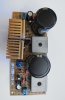
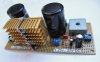
Please help. I use my own built 5AMP LM338K based 1.25V-25V power supply set at 9V.
I use velleman MK120 kit. The two pieces light source and light sensor work fine when powered by separate 9V batteries.
My problem is that I need to power them from same power source. Then they do not work.
Here is light source schematic: https://www.velleman.eu/downloads/files/schema/transmitter.jpg
Here is sensor schematic: https://www.velleman.eu/downloads/files/schema/receiver.jpg
Manual: **broken link removed**
Please help. I use my own built 5AMP LM338K based 1.25V-25V power supply set at 9V.
") from separate bateries.
from separate bateries.