Hi!
I want to build an ESR meter ...first of all i would like to know if you think
it's a useful tool and better than capacitometer on checking defected
capacitors?
second thing... i need heeelp! i know the basic principles of the way it
works, but my knowledge aren't enough to design one!
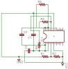
i prefer to use a wheatstone bridge, i have seen many schematics
and i think it's more easy to build it that way...i also prefer to use
the tl084 op-amps which i already have and i can buy a galvanometer
or use my analog multimeter to read my results! although i would like to listen
any other opinions on my design as long as it has nothing to do with microcontrolers! i don't have knowledge on such things...i'd like my design to be simple and cost effective and above all to do its job!
ready "examples" are acceptable...
Thanks in advance everyone willing to help me.
I want to build an ESR meter ...first of all i would like to know if you think
it's a useful tool and better than capacitometer on checking defected
capacitors?
second thing... i need heeelp! i know the basic principles of the way it
works, but my knowledge aren't enough to design one!
i prefer to use a wheatstone bridge, i have seen many schematics
and i think it's more easy to build it that way...i also prefer to use
the tl084 op-amps which i already have and i can buy a galvanometer
or use my analog multimeter to read my results! although i would like to listen
any other opinions on my design as long as it has nothing to do with microcontrolers! i don't have knowledge on such things...i'd like my design to be simple and cost effective and above all to do its job!
ready "examples" are acceptable...
Thanks in advance everyone willing to help me.
Last edited: