Electro Tech is an online community (with over 170,000 members) who enjoy talking about and building electronic circuits, projects and gadgets. To participate you need to register. Registration is free. Click here to register now.
Welcome to our site! Electro Tech is an online community (with over 170,000 members) who enjoy talking about and building electronic circuits, projects and gadgets. To participate you need to register. Registration is free. Click here to register now.
The square wave has many different frequencies while a sine-wave only has one...run it through an ideal bandpass filter to only have the one frequency remaning for a sine-wave? That would be one insane bandpass filter.
A square wave can be thought of as a very large number of ODD hamonics added together (of course it really isn't) so if you build a low pass filter with the cut off well below the 1st odd harminic you will have the square wave convertor.
It also depends on whether you want to vary the frequency of the square wave, in fact I don't know if it's possible with a vairable frequency input. You can convert a triangle to sine with a special non-linear converter but it doesn't work with a square wave.
Can some one tell me what a Band Pass Filter and a Low Pass Filter? I'm not a electrical engeneer nor a comp genus. I simply have a need to turn a modified sine wave or step wave into a pure sine wave. I have a 3000 watt modified sine wave inverter, I already have my voltage and the hz are right I just need to change the sine wave so I can operate every thing in my house. Sensitive electronics and such. It's like i have a incomplete inverter. They stoped at the modified sine wave and didn't go ahead and filter it out to a pure sine wave. It's hard for me to believe there's no way to do this. Also is there any way to use a comp or parts from old comps to build something to do this? Any ideas will be appreciated. Thanks
In that case, you need an inductor as well as a capacitor, in fact to do a good job of it you need several inductors and capacitors and they'll be pretty bulky too.
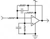
It can be done with two stages of integrators, the first one converts the square wave to a triangle wave, and the second stage converts the triangle wave to a sine wave. If the input frequency varies widely then the output amplitude will vary.
Here is a typical schematic, two identical stages are required
Hi all,
I need a electronic circuit to convert squre wave into
sine wave using appropreate filters.the coverted wave iwant to transmit through IR.
raju chennai
Hi all,
I need a common electronic design circuit for DC regulated power supply- buck- boost converter for a given input voltage variation , load current and output
voltage
HAi i made a square wave inverter but i need to convret the out put wave form to modified sine wave or pure sine wave is there any circuit for that please mail me any know about this please it is urgent i need to submit my project on 8th may please HELP ME........PLEASE.........
my mail i d is prasanthbhavana@gmail.com
please mail me about this PLEASE..........
If you want a modified sine-wave inverter then you must make a modified sine-wave inverter. You need a different transformer than a square-wave inverter because the peak voltage of a modified sine-wave is 1.414 times higher. It needs a digital logic circuit to make the modified sine-wave.
If you want an inverter with a pure sine-wave then you must make a very complicated pure sine-wave inverter circuit.
If you try to filter the output of a square-wave inverter with a 50Hz filter with a huge inductor and huge capacitor then the resistance of the inductor will reduce the output power. When the load is removed then the inductor and capacitor are series resonant and will short the output.
A square wave can be thought of as a very large number of ODD hamonics added together (of course it really isn't) so if you build a low pass filter with the cut off well below the 1st odd harminic you will have the square wave convertor.
Correct logic but wrong term. There is no such thing as a 1st harmonic. There is the fundamental frequency, next comes the 2nd harmonic (an even harmonic), then the 3rd (an odd harmonic), etc.
I know it sounds wrong but harmonics are named starting with the 2nd
Actually you misread what he put, your quote clearly says "first ODD harmonic" - bit of a strange way to put it, but actually perfectly correct. Presumably English isn't his first language?.
I am working with a feedback circuit for a sensor. I excite the sensor with a sinesodal voltage of aroung 50-200mV and 1K-500KHz. The output of this sensor is to read and so it is amplified. Now I need to put back the output voltage to 50-200mV since it is a feedback. I tried to use an AGC for this purpose but turned out to be real complicated for low amplitude signals. So I thought of using an diode clamping circuit to serve my purpose. But this gives a square wave of different harmonics. I need to convert this to a sine wave to avoid this. Can you suggest me any circuitry to serve my purpose. Can you also suggest any simple circuitry for AGC if any. Kindly do this help.
I do not know your name and I apologize for addressing you using your username. You were talking about an AGC circuit if you want the amplitude to vary less. Can you suggest me an simple AGC circuit with couple of opamps, resistors and capacitors. I really need an AGC which can control my amplitude in the range of 10-100mV.
This site uses cookies to help personalise content, tailor your experience and to keep you logged in if you register.
By continuing to use this site, you are consenting to our use of cookies.