Continue to Site

Welcome to our site!

Electro Tech is an online community (with over 170,000 members) who enjoy talking about and building electronic circuits, projects and gadgets. To participate you need to register. Registration is free. Click here to register now.

  • Welcome to our site! Electro Tech is an online community (with over 170,000 members) who enjoy talking about and building electronic circuits, projects and gadgets. To participate you need to register. Registration is free. Click here to register now.

Help in using transformer and voltage regulator...

Status
Not open for further replies.

yusuf

Member
Hello friends.

I have a transformer which is 18v-0v-18v with center taped..
And I have 8v and 12 voltage regulators which are 7808 and 7812.

I want to arrange this regulator in the transformer to gain 12v and 8v output dc and current 200ma..

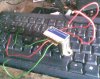
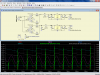
I have attached the Transformer image which I have ....so please have a look...

I want to gain 8v and 12v directly from 18v transformer..
I don't want to gain 8v by adding the 8v regulator at the output of 12v...

Thanks in advance...
:)
 

Attachments

  • Transformer.PNG
    Transformer.PNG
    5 KB · Views: 172
  • Orginal_trans.jpg
    Orginal_trans.jpg
    404.7 KB · Views: 222
hi,
That transformer could be used for +12V and +8V [7812 & 7808] regulators but it will be very inefficient.

If you dont mind wasting a lot of power as heat it can be done.

Whats the current rating of the transformer.??
 
Last edited:
The current rating of transformer is 500ma.

hi,
Look at this option for using your transformer.

Note the 5Watt resistors and the heat sinks for the 78XX Vregs.
 

Attachments

  • DualPsu1.gif
    DualPsu1.gif
    15.8 KB · Views: 219
Very very very thank you my friend..... for your help
I have some questions below regarding the circuit above......... so please..... answer...

1)What is the value of R4 & R3 and R2 & R1, is it in ohms , kilo ohms or mega ohms !

2)What is the use of R4 & R3 and R2 & R1 !

3)Is is using full wave rectification or half wave rectification !

4)Will the center wire of transformer will be common ground ! (You can see at my images of the transformer above , the secondary winding has two green color wire and one red color wire in middle).

5)How can we reduce or increase the output current !

6)Will the 12v output can drive 12v relay (Relay needs 60ma to work properly on 12v).

7)What is the advantage and disadvantage of this PSU !
-------------------------------------------------------------------------------

Friend , I have mentioned some question please give the answer...
As I am asking this question because I am new In electronic and need some help to create this PSU..

Thanks in advance...
And Thanks for co-operation...
:)
 
Very very very thank you my friend..... for your help
I have some questions below regarding the circuit above......... so please..... answer...

1)What is the value of R4 & R3 and R2 & R1, is it in ohms , kilo ohms or mega ohms !
All the values are Ohms.
NOTE: R1 R2 are just dummy loads for a 200mA test ONLY, you do not fit them.!


2)What is the use of R4 & R3 and R2 & R1 !
R3 and R4 are used to drop the voltage inputs to the regulators, in order to reduce the heat generated in them.

3)Is is using full wave rectification or half wave rectification !
Full Wave

4)Will the center wire of transformer will be common ground ! (You can see at my images of the transformer above , the secondary winding has two green color wire and one red color wire in middle).
The centre tap of the secondary winding is connected to 0V

5)How can we reduce or increase the output current !
The load you connect to the regulator outputs will determine the current!

6)Will the 12v output can drive 12v relay (Relay needs 60ma to work properly on 12v).
Yes.

7)What is the advantage and disadvantage of this PSU !
Work that out for yourself.:rolleyes:
-------------------------------------------------------------------------------

Friend , I have mentioned some question please give the answer...
As I am asking this question because I am new In electronic and need some help to create this PSU..

Thanks in advance...
And Thanks for co-operation...
:)

hi,
Hope that answers all your questions..;)
 
Thanks for your reply friend...
Some more questions ?

1)Can we turn on 8v and 12v supply simultaneously without any problem !

2)If suppose the Load exceeds the 200ma current then what will happen ! Will it work or will we have to do any changes in circuit !

3)If this circuit is used properly at all condition 24hr , then what will be the life expectancy of this circuit !
Friend As you said :
That transformer could be used for +12V and +8V [7812 & 7808] regulators but it will be very inefficient.

If you dont mind wasting a lot of power as heat it can be done.
Will this be a problem in power supply .... because I will drive cmos Ic's circuit on 8v rail !
And what was the reason behind friend about saying that it will be very inefficient !

thanks :)
 
Last edited:
Thanks for your reply friend...
Some more questions ?

1)Can we turn on 8v and 12v supply simultaneously without any problem !
Yes

2)If suppose the Load exceeds the 200ma current then what will happen ! Will it work or will we have to do any changes in circuit !
Your transformer is only rated at 500mA
You asked for 200mA for the 12V and the 8V, thats what is does.

3)If this circuit is used properly at all condition 24hr , then what will be the life expectancy of this circuit !
That depends upon the quality of the components that you use and if the devices are operated within their specified parameters.
Other than that.. a very long time


Friend As you said :

Will this be a problem in power supply .... because I will drive cmos Ic's circuit on 8v rail !
Why do think there maybe a problem using the 8V supply with CMOS logic, thats what its designed for.??

And what was the reason behind friend about saying that it will be very inefficient !

Efficiency is power in versus power out.
Power in = 18V *0.4A = 7.2 Watts
Power Out = 12V *0.2A = 2.4W.... 8V * 0.2A = 1.6Watts Total = 4Watts

So very approx eff: = 4/7.2 = 55%

thanks :)

This should be enough to enable to work out the rest for yourself.:rolleyes:
 
The power from the transformer is 18V x 1.414 x 0.4A= 10.18W, not 7.2W.
I don't see how Cmos logic ICs can draw 200mA, they might use 20mA max.

The voltage from the transformer is way too high so a lot of heat is produced in the resistors and in the 12V regulator.
 
Well, I arrived at a similar solution on the other site, but Eric and I differ in opinions on cap & resistor sizes.

See the attached schematic & simulation.
 

Attachments

  • 12v 8v linear power supply.png
    12v 8v linear power supply.png
    131.7 KB · Views: 191
I plugged in Erics' version of the schematic and simulated it.

Eric, you may wish to revise your version. The ripple on the input caps is quite high. Please see the attached.
 

Attachments

  • 12v 8v linear power supply Eric.png
    12v 8v linear power supply Eric.png
    132.9 KB · Views: 219
Last edited:
I plugged in Erics' version of the schematic and simulated it.

Eric, you may wish to revise your version. The ripple on the input caps is quite high. Please see the attached.

hi Sgt,
I intentionally used lower value smoothing caps in order to reduce the dissipation in the series power resistors and the regulators.

There is no point in trying to maintain a 18V*√2 , voltage on the smoothing caps in this particular circuit with an over rated transformer secondary voltage.

There seems a be a general misconception that a high value smoothing cap is 'best', this is not always the case.
A smoothing cap value should be chosen that gives just '+sufficient' ripple reduction at maximum specified current required by the load resistor at the regulated output, that maintains the required 2v to 3v differential voltage across the regulator.

Any increase in the value of the smoothing cap value over this 'optimum' value increases the heat generation in the series regulator and the peak current current thru the rectifier bridge.

Knowing that the OP is only driving a 50mA relay with the +12V and CMOS logic with the +8V.
the power supply was designed to meet that application, using an unsuitable transformer.
Eric.
 
The power from the transformer is 18V x 1.414 x 0.4A= 10.18W, not 7.2W.
I don't see how Cmos logic ICs can draw 200mA, they might use 20mA max.

The voltage from the transformer is way too high so a lot of heat is produced in the resistors and in the 12V regulator.

You are incorrectly assuming that the smoothing caps are trying to maintain 18V *√2, which you would see if you take the trouble to examine the circuit, that is not the case.

There is deliberate high level of ripple on the smoothed pre-regulator voltage.
Although its not RMS, for the purpose of simplification I used RMS in my power calculation.

The power input is certainly NOT 18V*√2 * 0.4A.
 
Last edited:
The power input is certainly NOT 18V*√2 * 0.4A.
That was my thought too, but now that I've got my 'thermometer' icon working in LTSpice I ran a sim using two voltage generators (25V amplitude, 50Hz) to represent the transformer secondaries. With a 200mA load on each of the +12V and +8V rails my 'thermometer ' graphs show the average power total for the two generators is ~10W; close to AG's figure.
 
That was my thought too, but now that I've got my 'thermometer' icon working in LTSpice I ran a sim using two voltage generators (25V amplitude, 50Hz) to represent the transformer secondaries. With a 200mA load on each of the +12V and +8V rails my 'thermometer ' graphs show the average power total for the two generators is ~10W; close to AG's figure.

This sim shows the two circuits, 330uF versus 2200uF, reduced each to single 7812 [0.4A loading].

The plots are showing the dissipation in only the regulator.
Its clear that the dissipation is higher in the 2200uF version.

Using the LTspice 'CTL left click' function on the two Plot labels, show 3.5W for 330uF and 4.7W for the 2200uF versions.

With ref the rms/avg Voltage on the smoothing cap its 20.6V for the 330uF and 23.6V for the 2200uF.

EDIT:
Taking a simplistic approach using the actual 20.6V and 0.4A = 8.24W and the 10.18W quoted elsewhere. I would say my original guestimate of 7.2W was more realistic...
 

Attachments

  • AAesp11.gif
    AAesp11.gif
    53.1 KB · Views: 203
Last edited:
Eric, you are comparing apples to oranges, as you did not include the current limiting resistors. Eliminating the resistors changes the circuits a great deal, and of course the power dissipation will be higher with the higher capacitor.
You are also placing a 30 Ohm load resistor on the outputs, which is a 400mA load instead of the specified 200mA load.

Attached is a corrected comparison that has the current limiting resistors and the correct 200mA load, which demonstrates that the version with the 2200uF filter cap before the resistor not only has lower power dissipation in the regulator, but less ripple on the output as well.
 

Attachments

  • 12v 8v linear power supply comparison.png
    12v 8v linear power supply comparison.png
    128.8 KB · Views: 191
Last edited:
Eric, you are comparing apples to oranges, as you did not include the current limiting resistors. Eliminating the resistors changes the circuits a great deal, and of course the power dissipation will be higher with the higher capacitor.

Attached is a corrected comparison, which demonstrates that the version with the 2200uF filter cap before the resistor not only has lower power dissipation in the regulator, but less ripple on the output as well.

hi SW,
I removed the resistors in order to show the total Wattage for each version, which was the point of my original argument.

I cannot see what is being disputed here, all I am saying a bigger capacitor is not required as it will increase the overall heat generation, thats why I say a 330uF will be a better choice.

Do you disagree with this basic statement.??
ie: the 2200uF will increase the overall dissipation compared to a 330uF in this particular circuit.???

Eric
 
Last edited:
For minimum power dissipation, I agree with Eric. You want the smoothing caps after the resistors to minimize peak current (and thus power dissipation) in the transformer and diodes, and you also want minimum capacitance (with consequent high ripple) to minimize power dissipated in the regulators.

That may increase the output ripple of the regulators slightly, but normally they have so much 50-60Hz ripple rejection that it is not a problem for most applications.
 
hi SW,
I removed the resistors in order to show the total Wattage for each version, which was the point of my original argument.
Oh, I see. As far as total wattage, then yes.

I cannot see what is being disputed here, all I am saying a bigger capacitor is not required as it will increase the overall heat generation, thats why I say a 330uF will be a better choice.

Do you disagree with this basic statement?
ie: the 2200uF will increase the overall dissipation compared to a 330uF in this particular circuit?

The smaller cap will cause the circuit to have a lower total power dissipation. However, the larger cap being on the other side of the resistor, the power dissipation in the regulator, which is the critical element, will be significantly lower.

Also, with the values that you have selected for the 8v regulator side, at 200mA current, you will have excessive ripple on the output. As you can see in the attached simulation, with a 200mA load your Vin drops low enough that the 2v dropout of the regulator causes about 0.8v ripple on the output.
 

Attachments

  • 8v linear power supply comparison2.png
    8v linear power supply comparison2.png
    125.4 KB · Views: 208
Last edited:
I see the slight ripple on the +8V, but a simple fix is to change the 33R to 27R, that removes the ripple.

SW and Carl.
Please look at the OP's picture of the transformer in his post.
He states it has a 0.5A secondary at 18v/0/18v, to my eyes, using the keyboard background in his image as a reference, it looks a little small to me for that rating.

What you think.?
 
Last edited:
Status
Not open for further replies.

Latest threads

Back
Top