Electronic Circuits and Projects Forum


FM Transmitter Colpitt Oscillator

1 2 Last »
Results 1 to 10 of 13
Reply to Thread
  1. #1
    jewdai
    jewdai is offline

    Default FM Transmitter Colpitt Oscillator

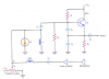
    I'm having trouble with the analysis of this circuit

    I understand (going from left to right) C1 takes the DC decoupled voltage from the Microphone, amplifies this via Q1, C2 decouples it again, then R6 and C3 Low Pass Filter it, but once we get to Q2, I am completly lost.

    My question is: How does this circuit act as a colpitt FM oscillator. Most of them I've seen are directly attached to the base.

    Secondly how does this circut actually accomplish frequency modulation: Please use math on me!!! (I know that it should change the delta F term in the equation cos(2*pi*fc*t + δF) to achieve FM, or more correctly: cos(2*pi*fc*t + δf*∫(messageSignal))

    How can I determine the Frequency deviation of this circuit?

    Please use Engineering terminology and Mathematical equations in your analysis: Im a Senior year EE.

  2. #2
    colin55
    colin55 is offline
    You may want a mathematical analysis of the circuit but can you explain the purpose of the 4p7 and 10n capacitors?
    Last edited by colin55; 23rd December 2009 at 07:01 AM.

  3. #3
    mneary
    mneary is online now
    Even without the math, it's a horrible circuit.

    Frequency deviation is accomplished by changes to the base voltage. This affects the Base-Collector capacitance. The tuned circuit is also changed when anything gets near the antenna and of course it drifts as the battery wears down.
    de KI6RWX

  4. #4
    jewdai
    jewdai is offline
    Quote Originally Posted by colin55 View Post
    You may want a mathematical analysis of the circuit but can you explain the purpose of the 4p7 and 10n capacitors?
    the 10n is prolly part of a LPF and the 4p7 is prolly part of the colpitt oscillator at the end.


    I realize this is a horrible design becuase the Qpoints are terrible (biasing Q1 at .9 volts doesnt allow for much negative voltage)

    Can you explain how it changes the capacitance, my semiconductor theory about BJTs is a bit rusty.

  5. #5
    jewdai
    jewdai is offline
    My goal is just to build a simple transistor level FM transmitter for my own amusement. More of an exercise on what I've learned as an engineer because I want my masters degree to be in Communications Systems and Signal Processing

  6. #6
    BrownOut
    BrownOut is offline
    I don't consider this a colpitts oscillator. Please see this thread for more information. There is a link to a pretty good analysis in that thread.

    Edit: My bad, we were discussing a different transmitter in that thread, but some of the discussion might still be useful. I have an article on your transmitter, but I can't find it right now. If I run across it, I'll post.
    Last edited by BrownOut; 23rd December 2009 at 03:33 PM.
    Lions and tigers and bears, OH MY!

  7. #7
    JimB
    JimB is offline
    Quote Originally Posted by jewdai View Post
    My goal is just to build a simple transistor level FM transmitter for my own amusement. More of an exercise on what I've learned as an engineer because I want my masters degree to be in Communications Systems and Signal Processing
    You are an engineer, and you are doing a Masters Degree, and you are bothering to analyse a toy circuit like that?
    The circuit has so many shortcomings that is is does not come up to the level of "bad".

    Do your self a favour and analyse the circuit of a REAL FM transmitter, one which has a defined, stable frequency, one which has sensible coupling to a defined antenna and harmonic supression filters.
    One which has an output power of more than a milliwatt or so.
    One which has defined modulation characteristics, adjustable deviation, a deviation limiter and appropriate AF frequency response.

    JimB
    Experience is directly proportional to the value of the equipment ruined.

  8. #8
    jewdai
    jewdai is offline
    I would also like to actually build it, for fairly cheap. So I'm looking at what I can get.

    Could you provide me with places that have such clearly explained and defined schematics? It becomes rather difficult to find such high level designs. I would really rather work at the transistor level (i.e., no OPAMPs or ICs, including multipliers)

  9. #9
    rahul.sadtm
    rahul.sadtm is offline
    As u know that u can provide arbitory signal from microphone, when this signal reaches to the base of Q1, it triggers your output which you will get at its collector and the thus the voltage at the base of Q2 will change and according to this voltage variation Q2 will generate the output at its collector.

    finally you can see as your base voltage varies your fm frequency varies and hence you get the frequency deviation.....

    To see it clearly you should go for its simulation...

  10. #10
    mneary
    mneary is online now
    I don't think modeling this circuit is practical. It depends on the changing output admittance (real and imaginary) of a transistor as its base voltage changes. I don't expect you will find such a detailed model of the 2N3904.

    Somebody probably built this circuit either intentionally or by accident discovered the frequency varied as the base voltage.

    If you want an inexpensive circuit that you can model and understand, build a real Colpitts oscillator and use a small varactor in parallel with its main tuning cap.

    I found this real example in this presentation: http://www.technology.heartland.edu/faculty/chrism/data%20comm/Power%20Points/ECS%20PPTs/ch06.pps
    Attached Images
    de KI6RWX

1 2 Last »
Reply to Thread

Similar Threads

  1. ¿1 Hz oscillator?
    By LApprenti Sorcier in Electronic Projects Design/Ideas/Reviews
    Replies: 32
    Latest: 13th May 2010, 09:23 PM
  2. First oscillator!
    By joshd963 in Electronic Projects Design/Ideas/Reviews
    Replies: 22
    Latest: 22nd July 2009, 10:49 PM
  3. FM transmitter [Oscillator Help]
    By chicaman in Electronic Projects Design/Ideas/Reviews
    Replies: 40
    Latest: 14th April 2009, 03:11 PM
  4. FM transmitter oscillator question
    By shehry in Electronic Projects Design/Ideas/Reviews
    Replies: 5
    Latest: 21st March 2007, 10:55 AM
  5. Needed: Good transmitter/oscillator
    By zachtheterrible in General Electronics Chat
    Replies: 2
    Latest: 6th August 2004, 05:45 AM