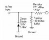
I'm using a voltage divider to drop the voltage that I sample from the ignition of my motorcycle. The divider is set to drop the ignition volts from 12v to 4v (1/3 the original). The divider consists of a 220k-ohm R in series with a 110k-ohm R, from 12v ignition source to ground. Output is taken across the 110k R, which should result in 4v. There is also a 5.1v zener diode across the output, which is supposed to limit any extraneous voltage spikes. However, my output volts is always around 3.15v, even at a steady 12v dc applied across the divider. I've measured the resistors and they all check out, even the applied volts checks out. I've varied the sizes of the resistances and it doesn't change much. When I took the zener out, the output went to the proper voltage.
I read, recently, that a zener won't operate properly if its current is restricted to less than 3 or 5 ma. Do you think that's what is happening in this case? I'm concerned that if I take the Zener out, extraneous voltage spikes might damage my circuitry down the line, one circuit being a Basic Stamp microcomp. that needs to be restricted to inputs of 5v or less
Thanks
PO'T
")
