Hi,
Since I've been doing lots of work with DIYing switch mode power supplies and portable applications, I needed to measure current quite often, in ranges from up to 5A, down to <1mA (standby current for uC). Getting my multimeter in series with the power supplies is a hassle, plus, at low currents, the voltage drop across the multimeter becomes unacceptable...so I need another one to measure the 'actual' power supply voltage my device is seeing.
So, I just spent 20 minutes with eagle coming up with a very simple and cheap little 1A power suppliy with selectable voltages. There are LOTS of these schems on the internet I know, but I haven't seen one with in built current measurement - which converts the current draw to a 0v referenced voltage, with selectable ranges, handy to plug a multimeter in in its DC volts range.
It measures current on the high side with a fairly large current sense resistor (a whopping 0.1ohms as oppoosed to the mili-ohm range) and a very cheap LM358. Low side current measurement is easier, but makes voltage regulation a bit harder. Of course, one could add a microcontroller, some PWM, precision reference etc.. but then it starts to get messy, and the LM317's regulation is pretty good on its own.
Designed to take DC input from your average wall-wart power supply, or anything you have to hand...I have many laptop PSU's, ATX psu's...etc.. so no point in reinventing the wheel by including a transformer and rectification.
Please note: not all the parts have values, as I couldn't be bothered to calculate them for the voltages. Thats the easy part and comes later.
Criticisms welcome!
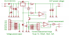
") I added the opamp because I was planning on adding a microcontroller to it, and the ADC requires a 0v referenced voltage (thus the opamp voltage follower as a buffer). Although of course I omitted it, it does form a uilding block, allowing any ADC, or a comparator to be used.
I added the opamp because I was planning on adding a microcontroller to it, and the ADC requires a 0v referenced voltage (thus the opamp voltage follower as a buffer). Although of course I omitted it, it does form a uilding block, allowing any ADC, or a comparator to be used.