Continue to Site

Welcome to our site!

Electro Tech is an online community (with over 170,000 members) who enjoy talking about and building electronic circuits, projects and gadgets. To participate you need to register. Registration is free. Click here to register now.

  • Welcome to our site! Electro Tech is an online community (with over 170,000 members) who enjoy talking about and building electronic circuits, projects and gadgets. To participate you need to register. Registration is free. Click here to register now.

Yesterdays Bibles

Status
Not open for further replies.

spec

Well-Known Member
Most Helpful Member
Today I was searching the net for information on radio frequency transformers and came across this great site (linked below).

My Dad had some of the antique linked books floating around the house in the 1950s and 1960s.

And I remember studying them intently wishing that I could understand more than the first couple of pages.

Not only is it great to see the books again but the basic theory is still relevant today.

Also, there is a picture of the site owner's cat, Chester, keeping an eye on things- as cats do.:cool:

spec

upload_2017-2-3_11-23-5.png

http://www.tubebooks.org/index.html
 
Last edited:
is there anything on interferences?

I wonder why you ask.:D

Here is a good book covering interference, but I suspect you really need a book on frequency stability.

(1.8) EMC for Product Designers by Tim Williams, 2007, Newmans, ISBN 978-0-75-0681-4 (later editions available)
Not a dry tome but humorous, surprising and insightful. Another book that illustrates what the wiggley amps are doing. Useful, not only for EMC design, but when specifying cabinets and racks and PCB layout. For example, this book helps when designing audio power amps for low distortion and good screening.

https://www.electro-tech-online.com/articles/books-articles-data.758/

spec
 
bloody hell, I guess I have to do the PCB layouts again....
Its essentially STs design, they should not be oscillating then.
AUD13 at ebay
 
Last edited:
bloody hell, I guess I have to do the PCB layouts again....
Its essentially STs design, they should not be oscillating then.
Hi CS,

Afraid you can have instability (or other similar effects) with any amplifier, even the very best with a perfect layout.

spec
 
Common-Point-Ground.PNG
hm, they sell TDA7293 kits everywhere, why am I the only one th have troubles.

These types of IC's are Very Susceptible to Ground Loops that cause oscillations.
All Ground traces should return separately to a Common Point as a ground.
 
I grew up with tube types. Many without cathodes - just the filament (DC powered), a grid and a plate (the first transistor of the age!!! - at least, how I still think of transistors, despite "hole" theory :banghead:).

My fav? RCA 6146A. 2nd fav - 5u4. With the plates glowing red and the blue haze of ionization, you knew you were sucking some serious amps...:woot:.

Yes, the same here with valves. My favorites were, EL84, EL34, and best of all KT66 ... KT88.

At one of the air bases I was at, a couple of us ran the camp radio station - it was a big booze up really because the station was right next to the NAAFI.

The distribution amps had four KT66s in parallel push pull and the violet corona used to dance to the rock music we played. Those were the days- not a care in the world.:joyful:

spec
 
View attachment 104063

These types of IC's are Very Susceptible to Ground Loops that cause oscillations.
All Ground traces should return separately to a Common Point as a ground.

I would prefer a solid ground layer with all ground connections making direct via to the ground layer. With the power amps running high ground currents, I think the star ground configuration ground trace leads would add significant IR drops across the traces, and secondly the ground trace leads prior to the ground point would act as EMI sources and possibly result in undesired feedback.
Of course grounding methods have been topics of hot debate for some time and I am just giving my thoughts on the matter. There was a time when I too used star grounding, but recent seminars on grounding have changed my thinking.
 
Yes, the whole issue of grounding is very difficult with high-gain high-power amplifiers and, when you consider the voltage and current gains involved, it is surprising that any audio amplifier can be made stable/have a good frequency response/have low distortion.

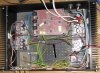
My view, based on years of messing with audio amps of all classes and types, and having all sorts of malfunctions, is that there are many facets to the problem and likewise there are many measures that need to be taken to get a fast but stable, optimally damped audio amplifier. You can get a clue by looking inside an audiophile amplifier where there are many extra bits and pieces to sort the performance.

One of the problems is that you can not only get instability in the amplifier overall but also in the sub amplifiers- even a humble emitter follower can oscillate.

In terms of layout, my feeling is that the radio frequency (RF) men have it. Quite simply, with RF circuits, the layout is either perfect or the circuit does not work.

So what approach do the RF men use: star point, ground planes, ground and signal ordering, screening, decoupling, and impedance matching. All of these, in my opinion, apply to audio amplifiers, with the exception impedance matching. In audio amplifiers impedance mismatch is used to give low distortion and good efficiency. For example, the output impedance of most audio power amplifiers is essentially zero ohms, but the speaker load is typically 8 Ohms. By contrast, the voltage amplification stage (VAS), in most high-end amplifiers has a high output impedance to drive the output stage with a constant current to reduce the inherent distortions in the output stage.

But there is a further consideration: ground current minimization. This means aiming at zero ground current, both direct and induced, and with careful design/layout you can get close to this with split supply line amplifiers. With single supply line amps you haven't got a chance, by definition. But you can minimize the effects of ground currents by having low resistance earth paths with hefty ground planes and wires.

You can inadvertently introduce ground current, not only by parasitic coupling but also by decoupling capacitors and, if you are not careful, you can inject noise and hash from the supply lines into the ground line- especially troublesome with with none linear amplifiers like class AB and D. This is a major advantage of class A where the supply line signal still resembles the audio signal but, with class AB, the supply line signal is a witch's brew of half wave rectification and xover artifacts.

Where star points (and signal ordering) are fundamentally important is in the power supply; the power supply has a surprising effect on practically every aspect of audio amplifiers. Also, with power supplies and high current paths in the amplifier, low resistance wiring is important. Similarly, low effective series resistance (ESR) capacitors are beneficial. I think Tony Stewart will advocate this.:cool:

Here endeth the sermon.:facepalm:

spec
 
Last edited:
round and round we go, it must have to do with the ground and with interferences. Pulled everything out of the house and its quiet. Bought the boook at ebay for AUD13, doing well on our employee road map, next book to read this year.
Guess will shorten and twist the transformer leads, separate signal and current grounds and what not. Maybe cook up a new xover 2 layer, bottom is ground plane and top is the other stuff. Has to be 24dB instead 12, so need new board anyway.
 
hm, they sell TDA7293 kits everywhere, why am I the only one the have troubles.
You're not. Audio power amplifiers are notorious for oscillations, extreme grounding sensitivity, and other headaches. If there is a suggested pcb layout in an app note, follow it to the micrometer and decouple the doors off of everything.

ak
 
Today I was searching the net for information on radio frequency transformers and came across this great site
I have some of those books, very dear old friends. I'm combining my work and home office libraries, and have been traveling down memory lane with some of the analog bibles.

ak
 
I have Made Lots of these over the years and Never used Ground planes, but I always use a common point ground (Star Ground).
Never had Any Problems.
Ground Planes Help Stop Hum and interference through the Air.
But Don't prevent Ground Loops.

Can you show us your PCB Layout?
 
the process of elimination: just connected the inputs of 2 monoblocks, hum is still there. Disconnect it, buzz is gone.
I am aware, it has to be shielded. I got short shielded cables for each monoblock to the xover, but that does not help. Plus, just one of these twisted cables with the xover hanging on it, does not generate noise either, when I hang it outside the enclosure. Inside it makes the same amout as a shielded cable. Regardless, if I just connect the signal or signal and ground. Has to be cable being an antenna. The monoblocks are quiet with open input, not catching anything.
Looping only signal through causes buzz, looping only ground through, no problem. So I guess, I need better shielding. It even buzzes, when I only touch the xover PCB board on the edges, not the copper.
 

Attachments

  • jumperlead.jpg
    jumperlead.jpg
    501.2 KB · Views: 80
Last edited:
**broken link removed**
antenna cable does not help (foil shield plus copper wire shiled). Guess ground the shiled like in that link above. EMC bible is still on its way, the other bible does not help.
 
If your cat behaved like my cat does, she would be sprawled across the keyboard.

To me, the first tubes that caught my fancy were 6L6. I would turn off the room light and watch the soft red glow punctuated by intense blue ionization haze, which danced in step to the LOUD ROCK &ROLL MUSIC!!
 
Status
Not open for further replies.

Latest threads

New Articles From Microcontroller Tips

Back
Top