Continue to Site

Welcome to our site!

Electro Tech is an online community (with over 170,000 members) who enjoy talking about and building electronic circuits, projects and gadgets. To participate you need to register. Registration is free. Click here to register now.

  • Welcome to our site! Electro Tech is an online community (with over 170,000 members) who enjoy talking about and building electronic circuits, projects and gadgets. To participate you need to register. Registration is free. Click here to register now.

XOR Gate Circuit From Diodes

Status
Not open for further replies.
Hi
Here is the circuit in the file attached.
thank you very much
 

Attachments

  • XOR GATE USING DIODES1.jpg
    XOR GATE USING DIODES1.jpg
    313.9 KB · Views: 190
This is getting monotonous. Yet again, not a "Logic gate" or anything that is real-world usable. Just a circuit the happens to demonstrate an XOR function with switches and an LED.

Both switches ON means both sides of the LED have the same voltage, so no light.
Both switches OFF means both sides of the LED have the same voltage, so no light.

One on and the other off means power from the switch, through the bridge and LED, to the resistor to ground at the opposite side.

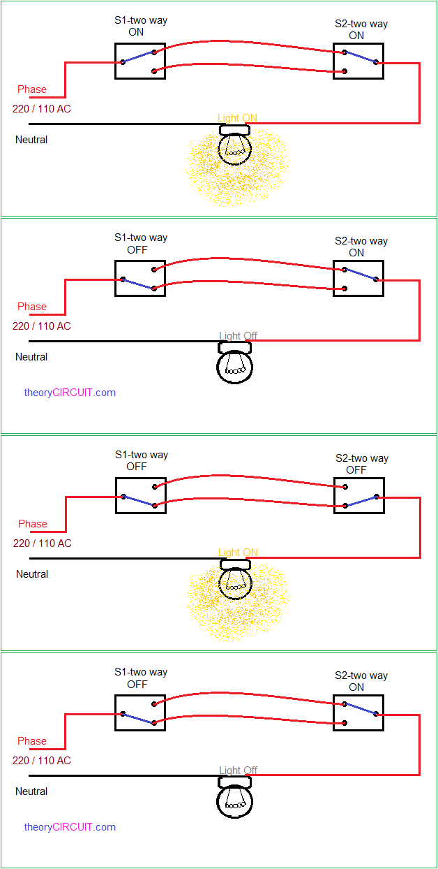
A two-way light switch circuit demonstrates an XOR function as well - it does not mean it's a "Logic gate".

two-way-light-connection.gif
 
It appears a large percentage of "logic gate" demonstrations on youtube have fundamental errors, but searching google images for diode logic gates, the majority seem correct in principle if not quite a practical implementation.

This is a good example that shows practical gate circuits and explains why the ones without transistors need to be used with caution:
 
Thanks
Can you show me please ;why both sides of the LED have the same voltage,in case of a=b=1
or a=b=0.
thank you for the answer
 
and what is the voltage difference between the sudes of the led in case of a=0 b=1
or a=1 b=0.
thanks
 
Just look at the diagram...

If both switches are ON, both inputs to the bridge rectifier are connected to the positive power; so the same.
If both are OFF, both inputs are pulled to 0V via the resistors; again the same!

If one is on and the other is off, the LED will drop whatever voltage it's rated at, at whatever current the power supply voltage (less two diode drops) and ground resistor set.

It will depend on the LED type and colour, as any LED and resistor combination.
 
Thanks for the answer.
But if both inputs are high then both A and B are sending current to the up side of the LED;
so it shouid be glowing.
Thanks a lot
 
Last edited:
If the currents were oposing each other; then you were right ; but here the currents from A and B are in the same side.
all the best
 
But if both inputs are high then both A and B are sending current to the up side of the LED;
so it shouid be glowing.
Have you never heard of an electrical CIRCUIT?
There is no return path to 0V. No voltage difference between the two switch outputs; no current flow.


Sorry to be blunt, but you need to learn the fundamentals, as you are trying to argue against the basic laws of physics & electrical principles.

I suggest you start with the free NEETS books, at module 1, and work though them.
 
Thanks for the answer.
If you say that the voltage from input B; influence on the bottom of the led via D3; and input A influence on the upper side of the led via D1;
then input A could influence on the botom side of the led via D4;
so you can say that the voltage on the bottom side of the led is twice more than the voltage on the upper side of the led(in the case of A=B=1).
thank a lot
 
Last edited:
Thanks for the answer.
If you say that the voltage from input B; influence on the bottom of the led via D3; and input A influence on the upper side of the led via D1;
then input A could influence on the botom side of the led via D4;
so you can say that the voltage on the bottom side of the led is twice more than the voltage on the upper side of the led(in the case of A=B=1).
thank a lot
You can say whatever you like, it does not mean it has any connection with facts or reality.

Again: See post #10.
 
Tanks for your answer.
Why it has no connection with facts or reality?
From input A you can get to the bottom of the led via D4
as you can get to the upper side of the led via D1.
So why the LED has the same voltage in both sides if a=b=1?
thanks a lot.
 
Last edited:
I repeat: There has to be a voltage difference across two points to cause a current flow.

If A and B are both connected directly together via the two switches, there is zero voltage difference and zero current flow between them.

It makes no difference what is between A and B, there is no current anywhere in that path and cannot be without an energy storage component (eg. battery etc) in the connection between A an B.

Remember that normal diodes do not conduct until the forward voltage reaches 0.6V or so across each diode.
There must be 1.2V + the LED forward voltage (around 1.8V) so 3V or so in total difference between A and B before any current flows between them.

If you just built the thing and used a voltmeter at various points you would be able to see for yourself.
 
Thanks for your answer.
The current will flow from A and B to the ground there the voltage is zero.
Thanks a lot
 
So in case of: A=1 B=0 or A=0 B=1;
Why all the voltage differance does not go the the ground instead
of going to the LED.
Especially if the intenaral resistence of the LED is greater then 7 ohm then it should go to the ground rather going to the LED.
Thanks a lot.
 
Last edited:
Again: See post #10.

If you want to learn, fine - start studying.
If all you want to do is keep posting nonsensical stuff due to lack of understanding, I'm not interested.
 
Thanks for your answer.
The question is not nonsense because of the rule that current always prefer to pass through the path
of the least resistence.
All the best
 
the rule that current always prefer to pass through the path
of the least resistence.
That in itself is not an accurate statement, and also does not necessarily apply to things that have a minimum voltage before they start to conduct, such as semiconductors
[Current will divide in inverse proportion to the resistance of each possible path, if adequate voltage exists to cause conduction].

But the fact is still that no voltage between two points means no current between them.

You are coming up with nonsensical arguments due to a lack of understanding of the basic principles involved.

Study and learn - and NOT from youtube!
 
Status
Not open for further replies.

Latest threads

New Articles From Microcontroller Tips

Back
Top