Continue to Site

Welcome to our site!

Electro Tech is an online community (with over 170,000 members) who enjoy talking about and building electronic circuits, projects and gadgets. To participate you need to register. Registration is free. Click here to register now.

  • Welcome to our site! Electro Tech is an online community (with over 170,000 members) who enjoy talking about and building electronic circuits, projects and gadgets. To participate you need to register. Registration is free. Click here to register now.

xenon flash power control

Status
Not open for further replies.

nebojsa ilic

New Member
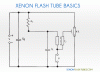
I need help with this circuit. F.T. Capacitor Cs is 330V 800uf, Ct is 400V 0.047uF, resistor is 5.1M, triger coil is TC-36.
In this circuit capacitor Cs discharge through flash tube with full power.
I want to control discharging power in steps of 1/2, 1/4, 1/8 ...
How this can be done?
 

Attachments

  • xenon-flashtube-principle.gif
    xenon-flashtube-principle.gif
    282.4 KB · Views: 132
If you add a rotary switch and extra Cs capacitors you could switch the extra Cs caps in & out, different values can be used to store different amounts of energy.
If you do this for safety put 470k resistors across the caps to discharge them when switched out of circuit.
 
Remember that current limiting can be reduced by ESR and series L but causes resonance with flash source capacitance and Q is L/ESR(total). Also energy transferred to flash is limited by storage cap dump voltage and V or C values used such that E=1/2 CV^2

So you can select different V with DC-DC regulator or different C with switches as Dr Pepper pointed out.

Some camera's with bounce flash use SCR resonant control with opto feedback to cut-off flash current depending on duration of delay of opto-feedback which demands inverse square intensity with rising round-trip delay of flash, to maintain required luminance or flux density at distance, X from flash.

Understand that a Xenon Fash is also like an SCR with a trigger voltage and cut-off current or in resonant mode ZCS for current when AC, but ESR of flash goes near infinite off, to near 0 depending on current in near 0 time (<1ns rise time of arc) then limited by root(LC) series rise to time .Both SCR and Xenon are negative resistance devices when switching, but Xenon is much lower negative ESR.(closer to zero)

also search for pre-existing solutions https://www.repairfaq.org/REPAIR/F_strbfaq.html#STRBFAQ_024
 
Last edited:
Basically, to reduce the power you can:
  1. use different sized Cs (as mentioned by dr pepper, above),
  2. change the charge voltage on Cs (requires a low-current-switching device in series with the charging supply), or
  3. control the conduction time of the lamp (requires a high-current-switching device in series with the lamp).
 
If you add a rotary switch and extra Cs capacitors you could switch the extra Cs caps in & out, different values can be used to store different amounts of energy.
If you do this for safety put 470k resistors across the caps to discharge them when switched out of circuit.
I have considered option to put extras capacitors but that increase nedeed space and cost.
Anyway, I want to figure out principle of old manual flashes and implement it in my project.
 
control board Carena, Hanimex, Cobra.png
Basically, to reduce the power you can:
  1. use different sized Cs (as mentioned by dr pepper, above),
  2. change the charge voltage on Cs (requires a low-current-switching device in series with the charging supply), or
  3. control the conduction time of the lamp (requires a high-current-switching device in series with the lamp).
High-current-switching device? Any link for circuit?
I found this on some russian site, it is circuit board marked EPT260-01B.
But, where are wires 1,2 and 3 connected?
**broken link removed**
 
Last edited:
Status
Not open for further replies.

Latest threads

New Articles From Microcontroller Tips

Back
Top