Continue to Site

Welcome to our site!

Electro Tech is an online community (with over 170,000 members) who enjoy talking about and building electronic circuits, projects and gadgets. To participate you need to register. Registration is free. Click here to register now.

  • Welcome to our site! Electro Tech is an online community (with over 170,000 members) who enjoy talking about and building electronic circuits, projects and gadgets. To participate you need to register. Registration is free. Click here to register now.

xbox mod

Status
Not open for further replies.

daviddoria

New Member
**broken link removed**
(dont know why link doesn't work , you have to copy and paste)

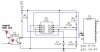
so the TIL198 is just for isolation, pretend i didn't care if it was isolated... what i'm gathering is that the hdd input ("working") is connected to the ENABLE pin on the 4017... this makes sense.. so when that changes state it either starts or stops counting... but what i dont get is that +5 is connected to the ENABLE pin always... this doesn't allow for it to ever start counting... correct?

"The disable input should be low (0V) for normal operation. When high it disables counting so that clock pulses are ignored and the count is kept constant." (from http://www.kpsec.freeuk.com/components/cmos.htm#4017)

can any one explain this?

david
 
The cause of opto application: we don't know the original HDD-led circuit (LED connected to GND or to +5V) so the opto-LED connected simply serial with HDD-LED.
When the HDD-LED lite, the opto enable the counting with 555 frequency.
 
sebi, but it seems like the output of the optocoupler doens't do anything because +5 is connected directly to pin 13 (enable) , disabling the counting... is this correct?

david

also, the 555 isn't set up in astable mode... whats going on??
 
No, not directly... via 68k "pull-up"resistor. And when the opto-led lite, the output transistor can pull down the pin13 to enable the counting.
The 555 circuit probably work, if not, i'm sure You can find a better low-frequency time-base, also with 555...
 
hmm... how does it "pull it down?"

and i still dont get how the 555 is pulsing... isn't there supposed to be 2 resistors connected to pin 7?

do you have any websites that talk about "pull down" and "pull up"?
 
When the logic input connected to positive with a resistor: this resistor called "pull-up" R. This method allow "pull down" the input with switch or transistor. The resistor need, because the logic input need logic level: 0(GND) or +(supply voltage). Floating pin make misfunction. The opto output is an NPN transistor, without LED driving not conduct, so without resistor the input floating.
 
Yes, this is a funny version of 555 astable. The capacitor charging from (HIGH) output via resistor, when the capacitor voltage rising to 1/3supply V the output level changed to LOW, and via resistor started the discharge.
BTW: i strongly recommend the original astable circuit of 555, don't like this cct.
 
i agree. i have seen the normal version everywhere

in a couple hours i'll redraw this circuit and can you tell me if its ok

thanks
david
 
sebi.... drawing this now...


i am using a 4n25 optocoupler... the input i do the + to the hdd monitor and the - to any ground.....

the output: do i run 5v to collector, emmiter to pin 13 on the 4017 (enable pin) ? and put the pull up resistor between +5 and the collector?

i will post this in a minute
 
NO, the resistor must be between pin13 and +, as the original draw shown. The optoLED in this case need a serial resistor about 1k. But i recommend: connect it serial with original HDD LED without resistor.
 
i'm still very confused.

on the right side of the optocoupler in my drawing, what am i supposed to connect the 2 leads to? and where does the resistor go?

thanks
david
 
I dont understand, why? Here is the correction.
 

Attachments

  • xbox.JPG
    xbox.JPG
    23.9 KB · Views: 213
AHHHH I GET IT!!!!!
thanks so much

david

edit**
actually, i almost get it... how is it that ALL the current goes to ground when the transistor is on? Wont some of it still go to pin 13 and it kind of be inbetween high and low?

dave
 
Status
Not open for further replies.

Latest threads

New Articles From Microcontroller Tips

Back
Top