Continue to Site

Welcome to our site!

Electro Tech is an online community (with over 170,000 members) who enjoy talking about and building electronic circuits, projects and gadgets. To participate you need to register. Registration is free. Click here to register now.

  • Welcome to our site! Electro Tech is an online community (with over 170,000 members) who enjoy talking about and building electronic circuits, projects and gadgets. To participate you need to register. Registration is free. Click here to register now.

Would this H-Bridge work???

Status
Not open for further replies.

pike

Member
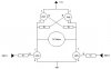
Hi guys i just need your opinions on this H-bridge all i need to know is that it will work.

I'm pretty sure that if one of the NPN transistors turns on only the opposite PNP transistor will turn on. When that transistor turns on it keeps the base hi of the opposite PNP transistor ensuring that only one of them turns on.

So my question is would this work??? By theory its sounds ok, I just need to know your opinions before i fry a set of expensive transistors...
 

Attachments

  • h-bridge_146.jpg
    h-bridge_146.jpg
    16.1 KB · Views: 731
Assuming the 12v supply is +ve, you have the C and E of the PNP transistor the wrong way round.

When a PNP is turned on, if Vce is greater than 0.6v, you will start to turn on the opposite PNP. You will then have nice hot smoking transistors.
To overcome this I suggest you put a couple of diodes in series with the base resistors so that as long as Vce of the PNP is less than about 1.8 volts, the opposite PNP is not turned on.

JimB
 
The circuit will work, with the changes pointed out by JimB, but be aware that when a transistor saturates there is a storage time before it turns off even tho the base current is off. If the storage time of the PNP is longer than the NPN (most likley), then there will be a momentary short circuit when both transistors on one side are on. If the time is short enuf, there may be no damage, but a current limiting resistor would be a good idea to start. Preventing saturation of the transistor is another option.
 
dont forget freewheel diodes
 
Hi guys i read your posts and decided to not bother with the protection of making sure that only one side of the trannistors turns on. This is because i can quite easily implement that into my PIC's code.

Instead i've added the diodes to make sure the voltage spikes from the motor starting/stopping from affecting other circuittry. I have also added the pull-ups and pull-downs to make sure that the transistor dont float around causing chaos.

What else do i need??? Do i need 1k ohm resistors on the red traces as marked??? Does this diagram look fine???

Styx: I dont know what you mean by freewheel diodes???

edit: forgot to attach picture
 

Attachments

  • h-bridge-3.jpg
    h-bridge-3.jpg
    24.6 KB · Views: 647
The diodes that you show are the free wheeling diodes. You don't need a 1k in the red leads because the 1k in the npn driver collector will limit the current. You still have not turned the pnp transistors around.
 
here's another h Bridge that others may find helpfull.
It only uses npn transistors.
I found it helpfull.

I found it on this web site, but can't find it any more.
here's my artists impression of it.
 

Attachments

  • usingnpns.gif
    usingnpns.gif
    6.3 KB · Views: 635
pike said:
Dude i'm puzzled by what you mean by that??? Why would you need higher voltages on the NPN bases?? :?

Because the emitter is always 0.7V lower than the base, so to turn the transistor fully ON you would need to take the base at least 0.7V higher than the positive rail. It would really need to be a fair bit higher than that, in order to give enough base current to the transistor.

It's a poor way to use a transistor as well - the voltage drop with the load in the emitter is much greater than with the load in the collector - which is the preferred way for using a transistor as a switch.

There are very good reasons for using PNP/NPN pairs, although you can use all the same, it's a far inferior design - requiring bigger transistors, larger heatsinks, and providing less power to the load.
 
Russlk said:
The problem with Screech's circuit is that a voltage higher than the positive rail is needed to drive the upper NPN. However, there are drivers designed to do that.

The upper NPN's are placed as emitter-followers, so you don't need a higher voltage to drive them, they'll just follow base voltage.
Off course, if base voltage is much lower then collector voltage then they'll waste more power and get hot.
 
Exo said:
Russlk said:
The problem with Screech's circuit is that a voltage higher than the positive rail is needed to drive the upper NPN. However, there are drivers designed to do that.

The upper NPN's are placed as emitter-followers, so you don't need a higher voltage to drive them, they'll just follow base voltage.
Off course, if base voltage is much lower then collector voltage then they'll waste more power and get hot.
A base drive voltage that's higher than the positive rail (with some current-limiting resistors) will allow the emitter followers to saturate, reducing the wasted power slightly, but at the expense of higher complexity.
 
Status
Not open for further replies.

New Articles From Microcontroller Tips

Back
Top