Continue to Site

Welcome to our site!

Electro Tech is an online community (with over 170,000 members) who enjoy talking about and building electronic circuits, projects and gadgets. To participate you need to register. Registration is free. Click here to register now.

  • Welcome to our site! Electro Tech is an online community (with over 170,000 members) who enjoy talking about and building electronic circuits, projects and gadgets. To participate you need to register. Registration is free. Click here to register now.

wiring help please

Status
Not open for further replies.

fefty

New Member
Hello All

I have a small lathe with forward and and reverse switch. Big problem is that I had to remove the 220V single phase motor from the lathe for transporting and I have lost the photo I took of the wiring hook up.

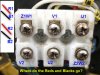
The terminal block is labelled:

Z1W1..........V1.............U1
O----------O----------O


O-----------O----------O
V2.............U2...........Z2W2

(ignore "-----" and "......" they were used to space the terminals)

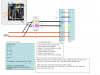
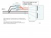
There are two sets of Red and Black wires R1, B1 and R2, B2 which come from the switch.

Can somebody help me connect R1,B1 and R2,B2 to their respective terminals on the terminal block.

Thanks in advance.

Fefty
 
on your motor data plate there should be a diagram of what wires go together for the rotation. if you trace those connections back to the switch end of the cable, you might be able to figure out the hook up.
 
Some snaps of my wiring (or lack of)

Here are some pictures of my problem
 

Attachments

  • terminal block.jpg
    terminal block.jpg
    65.8 KB · Views: 485
  • wiring.jpg
    wiring.jpg
    136 KB · Views: 873
Trace continuity between hot, neutral, B1, R1, B2, R2 for each switch position (fwd, off, rev).

I would start with the thesis that R1 and B1 are U1 and V1, and R2 is Z2-W2, and B2 is U2. If that doesn't map correctly, try other options or post your readings.
 
Meter readings

I tried the hook up you suggested but only got one direction to run. IE forward position - rotation at correct speed. Opposite or reverse position - no rotation.

Below are meter readings when switch was in 'forward and reverse' positions.

I did tie one red and black together before I shipped the machine home. So referring to R1, B1 and R2, B2 is ok.

When the switch was in 'Forward' position r1,b1 had 240 volts across them. r1,r2 240 volts, - r1,b2 0 volts, r2b1 0 volts, - r2b2 240 volts, b1b2 240 volts

When switch was in 'reverse' position the readings were:
r1,b1 had 0 volts across them. r1,r2 240 volts, - r1,b2 240 volts, r2b1 240 volts, - r2b2 0 volts, b1b2 240 volts.


Thanks

Fefty
 
I was anticipating that you would post power-off continuity readings. Sorry if I was unclear.

I'm happy that it runs forward without smoke.
 
hi fefty,

sorry for my english.
can you remove those wire again,


set the switch to forward then check continuity across r1r2,b1b2,r1b1,r1b2,r2b1,r2b2

set the switch to reverse then check continuity across r1r2,b1b2,r1b1,r1b2,r2b1,r2b2


check the resistance across u1u2,v1V2,Z1W1-Z2W2,u1v1,u1v2,u2v1,u2V2,
z2w2 U2,z2w2 V1


Please post the result.


note: unplug before checking the continuity.


**broken link removed**
 
Last edited:
Looks to me that Z1W1 and V2 are unused. Can you confirm this? You only have 4 wires so we have to assume a pair aren't used unless you had some jumpers installed somewhere.

For the motor to turn CW (clockwise) you need:
L1 -> U1+V1
L2 -> U2+Z2

For the motor to turn CCW you need:
L1 -> U1+Z2
L2 -> U2+V1

So basically all you are doing is reversing L1 and L2 (the mains) between V1 and Z2 to reverse the motor. U1 and U2 always stay the same. You need to determine which wires from the switch have L1 and L2 when the switch is in the forward reverse positions. I would measure this WITHOUT them connected to the motor. Alternatively you may just check them for continuity with the line input wires with the mains disconnected of course!

The motor wiring is pretty simple but until you provide us with the switch wiring details all we can do is make assumptions on how to wire the switch to it.
 
Here's what I think the switch looks like. You need to label the output wires with the appropriate labels. If we know which outputs are R1, R2, B1, and B2 I believe we can get you wired up.

**broken link removed**
 
More info

terminal Z1W1 has three wires from motor. Blue, Black and White
terminal V! two wires Yellow and White
terminal U1 one wire Red
terminal Z2W2 one wire Blue
terminal U2 one wire Red
terminal V2 two wires Yellow and Blue

Sorry no chance to test for continuity.

But thanks for help to date.

fefty
 
If jumides diagram is accurate you'd wire it this way...

B1 -> U1
B2 -> U2
R1 -> Z2
R2 -> V1

If the rotation is backwards swap R1 and R2. Again, this is assuming jumides diagram/evaluation of your first readings is accurate.
 
Success - Jumides' Solution spot on

Hello All

Thanks for the global effort. Everything working the way it should.

Hope the information proves to be helpful to others who may have similar problem.

fefty
 
So were we correct or did you figure out something different on your own? At least let us know if we figure it out! lol
 
Your solution spot on.

Hello All

Credit to your solution. No way could I have worked that out.

Thanks

fefty
 
Status
Not open for further replies.

Latest threads

New Articles From Microcontroller Tips

Back
Top