Continue to Site

Welcome to our site!

Electro Tech is an online community (with over 170,000 members) who enjoy talking about and building electronic circuits, projects and gadgets. To participate you need to register. Registration is free. Click here to register now.

  • Welcome to our site! Electro Tech is an online community (with over 170,000 members) who enjoy talking about and building electronic circuits, projects and gadgets. To participate you need to register. Registration is free. Click here to register now.

Wiring for DPDT relay & 2 switches (used for a reciprocating motor).

Status
Not open for further replies.

JBurnie

New Member
Hi all,

I'm currently designing a product which requires a reciprocating motion from a rack and pinion (driven by a 12V DC motor). I've been informed it's easy to do using a latching DPDT relay and 2 puch switches (one located at either end of the rack's stroke so it is pressed by the rack, reversing the current to the motor and so on in a reciprocating motion). I have a severe lack of electronic knowledge and, although I'm beginning to work on it, I need your help on this one.

I've found a latching DPDT relay:
**broken link removed**

and I assume I will use a couple of push-to-make switches?


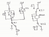
Could anyone explain / demonstrate how the components would be wired together?

I hope you can help!

Joe.
 
Hi,

I'm assuming you're wanting to use the relay contacts to drive the motor in one direction until it hits the end stop, then reverse it until it hits the other end stop, then repeat.

You didn't mention how much current the DC motor draws, so I'll assume that it's bigger than that latching relay you linked can handle. PS that relay is not simple to use with a single 12VDC supply and two SPST NO switches.

I've attached a diagram for what it sounds like you asked for; there are two standard [non-latching] relays, one to latch the direction based on the switches, and the other is to reverse the voltage and drive the motor.

There is a problem with this approach in that the motor is switched at full speed in one direction, then immediately switched in full speed in the other direction without a chance to slow down. You may have some large stall currents due to this. An improved version would use some electronics to delay the switch on in the new direction; e.g. once it hits the end stop the motor is turned off (perhaps slowed using dynamic breaking), then half a second later it is turned on the the other direction.
 

Attachments

  • motor oscillator relay.png
    motor oscillator relay.png
    11.2 KB · Views: 1,033
Hi,

Thanks for your reply, very much appreciated!

I'm assuming you're wanting to use the relay contacts to drive the motor in one direction until it hits the end stop, then reverse it until it hits the other end stop, then repeat.

- Yes that's exactly correct. The motor draws 500mA under max load but will be running at around 1/2 load normally so not quite as much current will be drawn (no-load current is 140mA). It's a geared motor with an output speed of 20RPM, one full reciprocation will take 8 seconds and only around 30 reciprocations will be required in any run (the slow speeds should reduce the stall currents to an acceptable amount?)

The circuit diagram is a little more complex to what I thought it might be! I'll do some more research and look into the components you've specified above.

Again thanks for your help!

Joe.
 
It might be easier just to get a latching DPDT relay with dual coils? They are available. That way you can just drive each coil with a pushbutton.

Re the reversing currents, this issue comes up a lot on the forum. You can fix it by simply using a current limited PSU, or a LM317 and a resistor to set a current limit. The reverse changeover current can never be higher than the set current limit. Adjusting the current limit can also give an accel/decel time, but you have to allow some overtravel past your limit switches.
 
Thanks Mr. RB, very helpful. I've found a latching real with twin coils:

https://www.electro-tech-online.com/custompdfs/2013/04/latch_relay.pdf

I've attached an image of the wiring diagram and how I thought it could be wired up... can anyone confirm this is right / wrong?

IMG_014.jpg

As for the stall currents do you think it will be a problem given the low speeds and loads? I'll maybe try it out with a fuse and if the fuse is blow then I can look into a current limited PSU or a LM317 & the relevant resistor as suggested..

Thanks again for your help!

Joe.
 
Below is a circuit using a standard DPDT relay in a self-latching circuit and two SPDT limit switches. D1 assures that the relay remains latched when the limit switch changes states.


Continuous Revers.gif
 
Last edited:
Hi all, I completed the circuit using a latching DPDT with twin coils (thanks Mr RB). It works exactly how it should! Thanks for all your help.

Joe.
 
Status
Not open for further replies.

New Articles From Microcontroller Tips

Back
Top