Continue to Site

Welcome to our site!

Electro Tech is an online community (with over 170,000 members) who enjoy talking about and building electronic circuits, projects and gadgets. To participate you need to register. Registration is free. Click here to register now.

  • Welcome to our site! Electro Tech is an online community (with over 170,000 members) who enjoy talking about and building electronic circuits, projects and gadgets. To participate you need to register. Registration is free. Click here to register now.

Wiring 240 V Water pressure pump to pressure switch

Status
Not open for further replies.

Gregory

Member
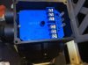
I have a singel phase 240 v water pump motor and have replaced the preasure switch with a new one .
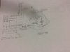
There was no circuit digram with the new preasure switch.
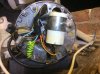
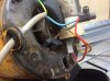
I will attach photoes of the rear of the motor and the preasure switch connectores .
I understand where the power supply goes but I am confused about the wirering of the motor.
Can you help me. Greg
 

Attachments

  • image.jpg
    image.jpg
    451.1 KB · Views: 550
  • image.jpg
    image.jpg
    1.1 MB · Views: 671
  • image.jpg
    image.jpg
    1.3 MB · Views: 603
Do you have a meter?
I think L and N go to power G is ground. It should not matter if L & N get mixed up.
U and V to to the motor and can be mixed up. G is ground or case or green.

With no water pressure:
There should be a connection between L and U could be L and V
There should be a connection between N and V could be L and U
There is a connection from G to G.

When pressure is high U and V are not connected to power.
 
Having connected power to the top 2 terminals and earth.
The power light comes on then punishing the reset button the reset light comes on then goes off after 4 seconds.
Placing the meter from earth to terminal u there is a 179 Volt.
Then from E to terminal v there is 0 volts.
The terminal V HAS continuity to N being Neutral .
There is no digraph on this unit connected to a preasure switch
I think the switch workes on current or bimetallic switch.
Can you help me with what connection I should do to U and V onto the cap start motor.
Thank you Greg
 
I noticed that it will turn off if there is no water!
This might be why it turns off after 4 seconds.
This would be good. If the well runs dry. I had to put a switch down in the well to turn off the power if the water level is too low.
"User manual in box"
I think you have it connected right.
I think this will work with out a pressure tank by reducing the power to the pump if the pressure is too high. And if the pressure is "0" for more than 4 seconds it will shutdown and require a reset.

If this things works with water pressure in it please tell me I am interested.
---edited----
**broken link removed**
 
Found it:Model: PS-WE21
Email: sales@bingo-sensor.com
https://www.bingo-sensor.com/Pressu...ter_Pump_Controller_PS-WE21.html#.V29Q6BLW2iA

1. Electric switch used in water systems.
2. It starts the electric pump automatically after a pressure decrease(taps opening)
and stops it when the fluid flow interrupts at the maximum pressure level of the
electric pump(taps closed).
3. Starting pressure is adjustable during installation, adjustment range: 1.0bar-3.5bar.
4. Joint screw: G1"male.
5. Completely replaced traditional pump control system composed of pressure switch,
pressure tank and check valve, etc.
6. Stop the water pump in the case of water shortage.
7. Customized setting.

Email or live chat or something! Ask for the manual that should have been in the box. (PDF) If you get a PDF please post it here.
----edit----
You could also try:
https://www.alibaba.com/product-det...131405204.html?spm=a2700.7724857.29.46.td2v2w
Now that I know what it is they are every where. No manual on line.
 
Last edited:
There is some more information on this unit **broken link removed**
There seems to be a copy of the manual towards the bottom of the advert.
You should be measuring voltages with respect to neutral not earth. (In the UK readings to earth should be almost the same as neutral is connected to earth either at the substation or where the mains enters the house. this may not be the case in your country.) The odd 179 volt reading may be due to the unit using a solid state relay output instead of contacts. If the load was not connected then you could be getting a reading via the snubber components. (Resistor and capacitor.) Have you verified that the pump works if connected directly to the power ?

Les.
 
Last edited:
Having connected the motor to the preasure switch and the unit is up and running.
I will attach photoes of the wirering circuit .
Hope this can help some others.
There is no preasure diaphrame the unit workes on current load.
Thank you all for your contribution
This unit will work with preasure in it but turn off when reach the set preasure on top of the preasure switch.
When the unit goes to 0 preasure it will turn on and build up preasure until the tap is turned off
and build up preasure for 3 to4 seconds.
The pump holdes preasure in the unit as long as there is not a leak.
If there is no preasure due to no water then the pump will shut down after 3 to 4 seconds.
 

Attachments

  • image.jpg
    image.jpg
    672.6 KB · Views: 457
  • image.jpg
    image.jpg
    1.1 MB · Views: 416
Last edited:
Status
Not open for further replies.

Latest threads

New Articles From Microcontroller Tips

Back
Top