Smartie
Member
Hey guys,
I want to build a wireless charger for a project I'm working on, please don't flame me with reasons to why I shouldn't go with this. I want help and advice on how to go with it")
I've started off with a 555 timer that has been tuned to give 130KHz output with a 50% duty cycle
but i need it to drive a LC Tank with almost 500mA output on the other end.
I've used this site LC Resonance Calculator
to calculate the inductance i need for my custom inductor (that i can wind by hand) and the value I have are 100nF for the capacitor and 13.5uH that will resonate at 137KHz.
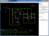
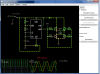
my next step is to oscillate the LC tank using the output from my timer and thought it would be suitable to use a H-Bridge, however, I'm not sure what components to use to drive it.
I've build a test circuit using this awesome tool Circuit Simulator Applet
If you want to test my circuit, goto that site, run the applet and import this code
so what are your guy's suggestions on what to do next?
what would be the best components to use for the H-Bridge?
just a side note, I've read somewhere that some MIT students managed to transfer power over a distance of 2 meters and they had the inductor oscillating at 10MHz. Do you think I could achieve that by improving this project?
Cheers
Roman
I want to build a wireless charger for a project I'm working on, please don't flame me with reasons to why I shouldn't go with this. I want help and advice on how to go with it
I've started off with a 555 timer that has been tuned to give 130KHz output with a 50% duty cycle
but i need it to drive a LC Tank with almost 500mA output on the other end.
I've used this site LC Resonance Calculator
to calculate the inductance i need for my custom inductor (that i can wind by hand) and the value I have are 100nF for the capacitor and 13.5uH that will resonate at 137KHz.
my next step is to oscillate the LC tank using the output from my timer and thought it would be suitable to use a H-Bridge, however, I'm not sure what components to use to drive it.
I've build a test circuit using this awesome tool Circuit Simulator Applet
If you want to test my circuit, goto that site, run the applet and import this code
Code:
$ 3 5.0000000000000004E-8 0.8031194996067259 42 9.92 50
w 232 152 200 152 0
r 200 216 200 152 0 470.0
w 200 216 232 216 0
w 200 216 200 248 0
w 200 248 232 248 0
c 200 248 200 328 0 1.0E-8 1.7852805509629803
g 200 328 200 344 0
r 200 152 200 88 0 470.0
w 200 88 296 88 0
R 88 72 56 72 0 0 40.0 5.0 0.0 0.0 0.5
O 392 184 392 136 0
165 232 120 248 120 2 0.0
w 296 88 360 88 0
w 360 88 360 152 0
174 264 328 328 280 0 1000.0 0.46040000000000003 Resistance
w 328 328 328 376 0
w 328 376 152 376 0
w 200 88 152 88 0
w 152 88 152 376 0
w 360 184 392 184 0
w 472 88 472 168 0
g 488 280 488 312 0
w 392 248 392 344 0
w 600 344 600 248 0
w 472 232 472 200 0
w 392 248 392 184 0
w 472 264 488 264 0
w 488 264 488 280 0
w 600 248 600 184 0
w 536 264 488 264 0
w 536 232 536 200 0
w 536 168 536 88 0
w 536 88 472 88 0
w 200 328 264 328 0
l 472 232 536 232 0 1.3500000000000001E-5 0.9140929757119651
c 472 200 536 200 0 1.0E-7 -26.748149409713033
159 472 168 472 200 0 1.0 1.0E10
159 472 232 472 264 1 1.0 1.0E10
159 536 264 536 232 1 1.0 1.0E10
159 536 200 536 168 0 1.0 1.0E10
I 392 344 600 344 0 0.5
w 552 248 600 248 0
w 552 184 600 184 0
w 392 184 456 184 0
w 392 248 456 248 0
d 416 88 472 88 1 0.805904783
S 152 88 88 88 0 1 false 0
g 88 104 88 136 0
x 91 57 155 60 0 10 Power Switch
r 360 88 416 88 0 10.0
o 10 4 0 42 5.0 9.765625E-5 0 -1
o 34 2 0 299 40.0 3.2 1 -1
o 45 4 0 33 20.0 0.8 2 -1
so what are your guy's suggestions on what to do next?
what would be the best components to use for the H-Bridge?
just a side note, I've read somewhere that some MIT students managed to transfer power over a distance of 2 meters and they had the inductor oscillating at 10MHz. Do you think I could achieve that by improving this project?
Cheers
Roman