Continue to Site

Welcome to our site!

Electro Tech is an online community (with over 170,000 members) who enjoy talking about and building electronic circuits, projects and gadgets. To participate you need to register. Registration is free. Click here to register now.

  • Welcome to our site! Electro Tech is an online community (with over 170,000 members) who enjoy talking about and building electronic circuits, projects and gadgets. To participate you need to register. Registration is free. Click here to register now.

Wire ring a 240 v single phase motor and capacitor

Status
Not open for further replies.

Gregory

Member
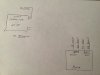
I have attached a drawing of the wires from the motor and capacitor.
I need help with the wire ring of the motor .
I have determined the run winding and the start winding with the resistance of the windings .
Where to connect the 240 v ac wires.
Could you help me with this .
Thank you Greg
 

Attachments

  • DFFD8786-5B71-420B-BAEC-8C9EBE8E28DB.jpeg
    DFFD8786-5B71-420B-BAEC-8C9EBE8E28DB.jpeg
    1.7 MB · Views: 380
The run winding is connected directly across power.
The start winding connects in series with the capacitor, then the two in series across power.

Is it a capacitor start or capacitor run motor? A capacitor start one is supposed to have a switch of some sort that isolates the start winding once the motor is spinning.

A capacitor run one has the start winding and cap permanently in circuit; no switch.

eg. https://4.bp.blogspot.com/-9NEezncA...s1600/capacitor-start-induction-run-motor.png
 
There is only a start capacitor and there is no switch in the circuit.
This motor is a pool pump motor and it had 3 wires now there is 4 as I opened the wires that had the start and run winding connected to get her. Cutting the start winding and then added a extra wires to enable me to change the rotation that is S1 black wire
 
If it is a pump, why do you need to change direction?
It is most likely a PSC motor, cap permanently connected. i.e. the two wingdings should be identical.
If so you can reverse direction with a simple SPDT switch, with centre off position.
Google PSC motor connection to get a diagram.
Max.
 
I want to change the direction as I want to use it on my pedestal drill

Many pump motors aren't made to have the direction changed easily. Do you have a model number or data sheet for the motor? Or post a photo of the wiring diagram that should be attached to the motor.
 
If it is not a PSC motor, (different resistance reading on each winding pair) then all you need to do is connect as it originally was, but reverse one of the winding pairs.
Max.
 
Something wrong with that DWG, both sides are identical connections??
Here is the SPDT switch version.
Max.
 

Attachments

  • PSC_Motor.pdf
    2.8 KB · Views: 134
I have been successful in doing what I wanted. The start winding has one side of the field connected to the run winding . I have cut the start winding wires being the thin one and attached a insulated wire and run it into the terminal box on the motor . Now I have 2 Ends of the start winding. Swapped the white and black over and connected the black to the white wire and the white wire to the brown wire which goes to the field winding in the motor . I have now reverse.
A motor that has written on it can not be reversed , can be reversed with a bit of work.
I anyone wants a drawing I can draw one up.
Hope this helps some one .
Good luck.
Thank you all for your input.
 
Many pump motors aren't made to have the direction changed easily. Do you have a model number or data sheet for the motor? Or post a photo of the wiring diagram that should be attached to the motor.
[/QUOTE
I did not have a model number or data sheet or a circuit. Digram of the motor.
Thank you for your help.
 
Status
Not open for further replies.

New Articles From Microcontroller Tips

Back
Top