Continue to Site

Welcome to our site!

Electro Tech is an online community (with over 170,000 members) who enjoy talking about and building electronic circuits, projects and gadgets. To participate you need to register. Registration is free. Click here to register now.

  • Welcome to our site! Electro Tech is an online community (with over 170,000 members) who enjoy talking about and building electronic circuits, projects and gadgets. To participate you need to register. Registration is free. Click here to register now.

wind powered baterry charger

Status
Not open for further replies.

brinda george

New Member
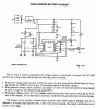
I cant read out the actual circuit description from the given circuit diagram.though i got some vague idea, i want to know the purpose of each component and the whole working.i want to know the charging path of each battery from LTC1042.And the use of LT1004-1.2,diode IN4001,and the MTP8NO5.is it available in the market? i like to do this as a project;can u give me a clear idea.
i am attaching the ciruit diagram, ic pin out diagram and other details .can you help me..
 

Attachments

  • wi mob charg.jpg
    wi mob charg.jpg
    420.8 KB · Views: 446
  • CRT.pdf
    114 KB · Views: 285
The circuit description is very clear and contains all the necessary information to build it.

The NiCad battery is used in cases the wind generator doesn't produce any output voltage (kind of standby power supply for the IC).

If the voltage supplied by the generator exceeds 13.5V the lead-acid battery is being charged.

If the battery voltage exceeds 15.1V the extra load is activated, consuming extra power, thus reducing the charge voltage and current and additionally force the wind generator into lower (safer) rpm range. You might experiment with the load resistance to make it as high as possible (for maximum braking action without exceeding the generator rating) and simultaneously disconnect the battery.

If the blades' radial speed become supersonic it's time to look for cover. :)

There is still some time of a few seconds left because the sonic boom occurs in the transsonic range of 0.97 to 0.98 Mach already. :D

If you live in an area where strong winds and storms are prevailing you better think about a prop with feathering mechanism.

Boncuk
 
thank u sir.
can we change the window limits from 13.8-15.1 to some other values by designing voltage divider network and zener diode.
i am true that CENTER is set by LT1004-1.2 and WIDTH set by 10K and 215k voltage divider n/w.
then what is the purpose of .1 microF from pin 2
 
Status
Not open for further replies.

Latest threads

New Articles From Microcontroller Tips

Back
Top