Continue to Site

Welcome to our site!

Electro Tech is an online community (with over 170,000 members) who enjoy talking about and building electronic circuits, projects and gadgets. To participate you need to register. Registration is free. Click here to register now.

  • Welcome to our site! Electro Tech is an online community (with over 170,000 members) who enjoy talking about and building electronic circuits, projects and gadgets. To participate you need to register. Registration is free. Click here to register now.

Will Header and socket hold this PCB OK?

Status
Not open for further replies.

Flyback

Well-Known Member
Hi,
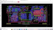
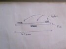
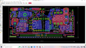
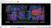
Will the right angled header be OK to hold this PCB as attached?...its only for prototype...never for production...
Its a Flyback SMPS (non isol) with ETD29 ferrite.

Header (right angled)
https://uk.farnell.com/multicomp/mc34775/header-2-row-r-angle-20way/dp/1593454?st=pin header, board-to-board, 2.54 mm, 2 rows, 18 contacts, through hole right angle, mc34

PCB socket housing
https://uk.farnell.com/harwin/m20-7831046/socket-pcb-0-1-10-10way/dp/7992025?st=m20-783

ETD29 transformer:
https://www.tdk-electronics.tdk.com/inf/80/db/fer/etd_29_16_10.pdf
 

Attachments

  • Flyback 30W.jpg
    Flyback 30W.jpg
    300.9 KB · Views: 208
What an..... um..... interesting board layout. The drunkard's–path routing is something you don't see often.
 
Thanks....thats a good explanation...just wishing i had a good bottle of London Pride to wash down now.....though look at the electrical viewpoint...perfect layout!...(well, within cost constraints)
I've been into co's where beutiful layout was failing EMC by a million miles, due to poor electrical layout.

But the riddle is, why does a 20way Right angled header not give electrical contact into the mating socket on the main PCB? Is it the stress to the sprung contacts in the housing?

Heres the inside of the mating socket...

What law of physics confirms that the electrical connection wont work?...or will it work?...for prototype only.....yes its only proto..but still needs to work nice and goodly
 
Last edited:

Attachments

  • 72WAY.jpg
    72WAY.jpg
    491.8 KB · Views: 191
Have you never disconnected a dual-row header? Disconnected a floppy drive or (pre-Sata) hard drive? Pulled a dual-row IDC ribbon cable from a pcb? It takes some force to pull one of these apart. Even a 2×8 cable can be difficult to pull out.

Rocking along the length is one way to get a stubborn connector apart. To reduce the effect of this mechanism, you could add "ears" at each end of the daughter board designed so that they just touch the main board when the header is fully seated.
 
Thanks FTP, for telling about Dis-insertion force...yes, for this reason i will try and use the smallest number of headers.

I may footprint a 72 way, but just use three 12 ways at end , middle and other end, say...and to be sure, i will solder the three sockets in with the mounted header(s) already in them...to get round solder hole size tolerance problems.
What do you think?
 
Sorry, I didn't mean to imply that with whatever number of pins, it would be too difficult to remove – just that there is little danger the board will fall out. Unless you're throwing it across the room against the wall.
 
The red board is supported only by a 1×6 header. About 50 of these have been in the field for 5 years and none have fallen off. Of course, this board doesn't have much mass.

No, I am not suggesting 6 pins or any greater or lessor number of pins for your application – just showing what has worked, since your real-world experience seems to be nil.

FB_IMG_1653042386654.jpg
 
No, I am not suggesting 6 pins or any greater or lessor number of pins for your application – just showing what has worked, since your real-world experience seems to be nil.
Thanks yes, real world and i dont meet very often,........though do you hazard that the 20 way header of the top post could actually work?.......some people have suggested to me that it wont work......but surely it will?.....(just for a prototype, i wont be launching it on a missile etc)
 
Sorry, not my circus, not my monkey. Please refer to my previous post regarding any recommendations about the number of pins you should or should not use.

To quell your insecurities and doubters, provision for
one of these blocks
at each end of the board.

SmartSelect_20220520-052917_Edge.jpg
 
Thanks, just also wondering, what about the attached method?
 

Attachments

  • pcb vertically.jpeg
    pcb vertically.jpeg
    17.8 KB · Views: 186
  • Vertical SMPS PCB.png
    Vertical SMPS PCB.png
    205 KB · Views: 192
Status
Not open for further replies.

Latest threads

New Articles From Microcontroller Tips

Back
Top