Continue to Site

Welcome to our site!

Electro Tech is an online community (with over 170,000 members) who enjoy talking about and building electronic circuits, projects and gadgets. To participate you need to register. Registration is free. Click here to register now.

  • Welcome to our site! Electro Tech is an online community (with over 170,000 members) who enjoy talking about and building electronic circuits, projects and gadgets. To participate you need to register. Registration is free. Click here to register now.

Why this cable on neon sign transformer?

Status
Not open for further replies.
That is the thing I am doing. I want to understand better short distance wireless energy transfer and build some simple circuits. Maybe I will build a Tesla coil or not, but I am learning.

One question. When people speak about magnetic resonance or resonance inductive coupling. What are they refering to? Why magnetic and not electric, capacitive or electromagnetic? Do the coils have the same inductance and for that reason people call it "inductive coupling"?

Good for you! It's nice to see some initiative taken by the learner ;)

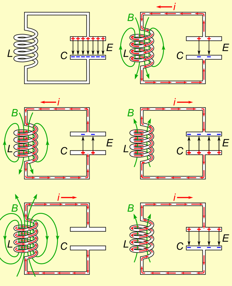
"Resonance" is a term referring to the natural oscillation frequency of an LC (that is inductor-capacitor) circuit. A simple Tesla Coil (Spark gap type) has two LC circuits (also referred to as "tank" circuits). The first, or "primary", tank circuit is made up of the main capacitor and the primary coil. Together they oscillate at a particular frequency based on the values of L and C. As the capacitor discharges it charges the inductor, and eventually the inductor begins to discharge and it starts charging the capacitor. This cycle repeats over and over again, and the rate at which it does this is called its "resonant frequency".

The secondary tank circuit is very similar electrically, though instead of having a high capacitance and a low inductance like the primary tank circuit, the secondary circuit has a high inductance and a low capacitance. The inductance comes from the secondary coil and the capacitance comes from the topload. They also have a "resonant frequency". The trick is to match the frequency of the secondary tank circuit with that of the primary tank circuit. When they're perfectly matched nearly all of the energy in the primary tank circuit is transferred to the secondary tank circuit by way of magnetic (or electromagnetic) coupling. As you know when you pass current through a coil of wire it creates a magnetic field. And when this field is oscillating, it can induce current in a nearby coil. If the resonant frequency of both circuits are matched, you get the maximum power transfer between the two. This is how energy is sent from one coil (the primary) to the other coil (the secondary) without being electrically connected.

Inductive coupling, magnetic coupling, and electromagnetic coupling are all referring to the same concept. When passing current through an inductive element you get a magnetic field, which is often referred to as an electromagnetic field because it is generated by electrical current.

Make sense?

I know you're not necessarily creating a Tesla coil right now, but I feel it is a perfect example of these concepts in action. I hope I didn't throw you off with all the Tesla coil terms--Most of them can still be applied to any coupled resonant circuits.

Matt
 
Good for you! It's nice to see some initiative taken by the learner ;)
...
First of all thank you very much for the detailed explanation.
Well, I have understood almost everything you have said and I have still some doubts.

1) I have asked to you about magnetic resonance/inductive coupling because it seems that electromagnetic coupling and magnetic coupling are similar but not the same. After reading your explanation I have understood that when you have a coil and the circuit draws energy in it, there is a changing magnetic field and that oscillating magnetic field can induce energy in a secondary coil. So electromagnetic coupling and inductive coupling can be seens as the same thing because electromagnetic coupling involves a changing magnetic field and for that reason it's possible to receive energy in the secondary coil.
But searching in Google I have found the next:
**broken link removed**
It seems that there is a small difference between the 2 kind of inductions. Of course, both involve the use of an oscillating magnetic field to induce energy in the receiver coil. But (and here is where I have the doubts) I think in magnetic resonance the inductance from the emitter and the receiver are the same, and in electromagnetic induction it's not necessary that L1 and L2 have the same inductance. In both cases it's used electromagnetic energy but it seems that in magnetic resonance there is an inductance matching between the two coils. Right or not?

2) When you speak about resonance on the LC I have understood that given a capacitance and an inductance there is only one resonance frequency. That is caused because there is "capacitive resistance" and "inductive resistance" in AC and it's called reactance. If you change the frequency there is only one specific frequency where capacitor and inductor have the same reactance. Right?
So it's needed to calculate the resonant frequency of the LC tank to obtain resonance, right?
 
Ok, just a couple of points:

1)
I have understood that when you have a coil and the circuit draws energy in it, there is a changing magnetic field and that oscillating magnetic field can induce energy in a secondary coil.
You will not have oscillations without a capacitance to go along with the inductance. When you apply direct current to an inductor it acts like a short, and when you apply alternating current to an inductor, it acts as a resistor. To be more accurate, this "alternating current resistance" is called "impedance", which consists of a resistance (a "real" number) and a reactance (an "imaginary" number). A common way of depicting this is called "rectangular form" and looks like this:

3fd5f3058c1af4ded63675eccee6185b-2.png


where "R" is the resistance and "X" is the reactance (whether it be capacitive or inductive). If the reactance is capacitive, then instead of R + jX it would be R - jX. You are absolutely correct regarding reactance -- it is the AC version of resistance.

2)
I think in magnetic resonance the inductance from the emitter and the receiver are the same, and in electromagnetic induction it's not necessary that L1 and L2 have the same inductance. In both cases it's used electromagnetic energy but it seems that in magnetic resonance there is an inductance matching between the two coils. Right or not?

Not. You can have magnetic coupling even when two inductive elements do not have the same inductance. Look at a standard transformer--One winding has a higher inductance than the other (unless it's just an isolation transformer, but let's not get into that right now), but they are still magnetically coupled.

Resonance does not require two coils. Resonance is when a capacitor and an inductor oscillate at their own natural frequency. Resonance is a characteristic of a capacitor and an inductor, not of two inductors.

3)
If you change the frequency there is only one specific frequency where capacitor and inductor have the same reactance. Right? So it's needed to calculate the resonant frequency of the LC tank to obtain resonance, right?

No, the frequency is an output, not an input. All you need to know is the inductance and the capacitance. The frequency is determined by the following formula:

a9b41afd1a1ab2acd9bf3c3b286607bb-2.png


where
f = the resonant frequency (in Hertz)
L = the inductance (in Henrys) and
C = the capacitance (in Farads)

You can stimulate an LC circuit with a much lower frequency, but it will still oscillate at the resonant frequency determined by the above formula.

Here is an animation showing the capacitor discharging which charges the inductor, and then the inductor discharging which charges the capacitor.

Tuned_circuit_animation_3_300ms.gif
 
Last edited:
QUOTE: "You will not have oscillations without a capacitance to go along with the inductance".
But Every Coil also has some Capacitance, so they have a "Free Air Resonance".
 
QUOTE: "You will not have oscillations without a capacitance to go along with the inductance".
But Every Coil also has some Capacitance, so they have a "Free Air Resonance".

Ahh, an excellent point, but I'm pretty sure that's not what the OP was going for.

I should have said an ideal inductor cannot resonate without a capacitor. Thanks for bringing that up chemelec.
 
Actual Neon Transformers Came in Two Different sizes. (I have a Few of Each of these Transformers and they produce a nice Yellow Spark.)
Normally rated at Either "15Kv at 30 mA" or "15Kv at 60 mA", Both at 60 Hz Output Frequency.

Some years ago I worked for a sign company sign transformers come in a lot of sizes. The 30 and 60 ma ones are the most common. As for voltage they come in most any voltage from around 2 KV to 20+ KV.

Some of the better solid state HF based ones are configurable for different or variable output currents making it possible for the signs to be dimmable which is fairly hard to do with old iron core transformer types.:cool:
 
Not Related to NEON Signs, But just a Comment.

The Biggest Transformer I had was 80KV at 100 mA.
It was an X-ray transformer with a 220 Vac Primary at about "30 Amps" if I remember Correctly.
It was Oil Filled and Weighed about 500 pounds.
WOW, What a BEAUTIFUL SPARK that put out!

I need it in my last job for testing Insulators.
 
QUOTE: "You will not have oscillations without a capacitance to go along with the inductance".
But Every Coil also has some Capacitance, so they have a "Free Air Resonance".
I am reading all the information that each one of you have posted and I am replying little by little to each post. It's all new information for me.

Yes, I have read that the coils also have capacitance. The main question is if designing a LC circuit you need to sum the coil's capacitance + capacitor capacitance to calculate the resonant circuit or not.

I have read very little and I have to read it again, but I think coil's capacitance is not included in the formula to calculate the resonant frequency of the LC tank. Right?
 
Ahh, an excellent point, but I'm pretty sure that's not what the OP was going for.

I should have said an ideal inductor cannot resonate without a capacitor. Thanks for bringing that up chemelec.
It's good to know what chemelec said. The questions I am asking are more basic because I know almost nothing about electronics. But it's very good to know all those small details.
 
I am reading all the information that each one of you have posted and I am replying little by little to each post. It's all new information for me.

Yes, I have read that the coils also have capacitance. The main question is if designing a LC circuit you need to sum the coil's capacitance + capacitor capacitance to calculate the resonant circuit or not.

I have read very little and I have to read it again, but I think coil's capacitance is not included in the formula to calculate the resonant frequency of the LC tank. Right?

The coil's capacitance is not included in the formula because it is so low compared to the tank capacitor's value, it's negligible (probably in the picofarad or femtofarad range, depending on the size of the coil). Suppose you had a million dollars and a penny. When counting your money, would you include the penny? Probably not, because its value is so low compared to the rest.

The resonant frequency formula is for an ideal inductor and an ideal capacitor.
I see, so the capacitance is too low to include it in the formula. It can be considered almost zero because it has very little effect on the final result.

The example about the amount of money is clearly demonstrative and it's very easy to understand.
I keep reading your posts to ask you more questions.
 
Yes, It is Near Zero, with a Few Exceptions.
A Coil With Thousands of Tightly Wound Turns will have Much More Inter-wire Capacitance than a Normal sized Coil.
So a High Frequency RF coil will have "Almost No Inter-wire Capacitance".

The Formulas are Also for IDEAL Coils and Capacitors.
They are Just a Guideline to get started.
Than you need trim the capacitor, if you want an Exact Resonance.
 
DerStrom8
I have asked a guy on the internet about what magnetic resonance exactly is and he has said the next

Inductive resonance means that two coils have the same resonant frequency. This term is used to make it clear between inductive coupling w/o resonance and with resonance. The system shown in the video has two identical coils which are expected to have a same inductance. and fine frequency tuning is accomplished by the variable capacitors. If you look the antenna, you can find that that antenna is composed of coil and capacitor which is the components of the RLC circuit.
 
DerStrom8
I have asked a guy on the internet about what magnetic resonance exactly is and he has said the next

Two dissimilar coils can still have the same resonant frequency. Once again, it all depends on the capacitor, not the coils themselves. The person you quoted mentions variable capacitors, which are adjusted to "tune" the coils to the same resonant frequency. His example uses two identical coils, but that is not absolutely necessary. Inductive coupling is when energy is transferred from one coil to another via a magnetic (or electro-magnetic) field.

His post is not incorrect, nor does it disagree with mine. It does, however, seem to be a bit misleading, as it leads to the assumption that two coils MUST be identical in order to have inductive coupling. This is not the case.
Reading all your comments I have a more clear description about what magnetic resonance is.

The next question is: Can two dissimilar coils have the same inductance? I know that is not critical, but it's a doubt that I have. I think that 2 dissimilar coils can have the same inductance, but I don't know if that is true or not.

I am still reading your above big post trying to digest all the valuable information you have posted.
 
Depends on your Definition of DISSIMULAR?
But Two coils of Different Diameters and or Wire Sizes, Can have the Same Inductance
 
Depends on your Definition of DISSIMULAR?
But Two coils of Different Diameters and or Wire Sizes, Can have the Same Inductance
With dissimilar I mean different diameter and or wire length.
So the answer is yes. They can have the same inductance even the length of the wires or the diameter or the cross section is different.
 
Resonance does not require two coils. Resonance is when a capacitor and an inductor oscillate at their own natural frequency. Resonance is a characteristic of a capacitor and an inductor, not of two inductors.
I was confused about that. I understood that 2 LC circuits are in resonance when they oscillate at the same frequency.
So resonance is when the LC tank resonates. It means that there is only one frequency where L and R shares a characteristic (reactance is the same at this point).

2 coils without capacitor or 2 LC tanks are coupled (not resonance, but yes coupling) when they oscillate at the same frequency. Or not? I am a little bit confused for that reason I am reading all the information you have posted because I think when the L2 coil receives energy from the L1 coil they are coupled. But, what about then they have the L1 and L2 have the same inductance? How is called that?
Because 2 LC tanks where L and R are matched is called a resonant LC tank. If you add a receiving LC tank (also L and C in resonance) it can happens the next:

Case A) LC emitter in resonance, electromagnetically coupled to receiver LC (L2 and C2 in resonance). But the tanks are not tuned to the same frequency. Example LC resonance tank 1 is tuned to 400 Hz, but LC receiver is tuned to 500 Hz. There is still energy transmission (so there is couplling between receiver and emitter). But LC circuits are not speaking the same language (400 Hz and 500 Hz).

Case B) LC emitter in resonance, LC receiver in resonance and both emitter and receiver are speaking the same language. In this case the resonant frequency of emitter and receiver is the same (400 Hz and 400 Hz). But inductance of the coils are different.

Case C) LC emitter in resonance, LC receiver in resonance and both emitter and receiver are speaking the same language (400 Hz and 400 Hz), and the inductance of both coils is the same.

Case A: RLC tank electromagnetically coupled to RLC receiver.
Case B: RLC tank magnetically (inductively) coupled to RLC receiver.
Case C: ?????
 
Status
Not open for further replies.

Latest threads

New Articles From Microcontroller Tips

Back
Top