Emantra
New Member
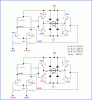
Here I have given you guys my simple ckt. I couldn't find out the fault.
The problem is that it doesn't work. This ckt is interfaced with the computer, when I have given the appropriate signal to the input the motor doesnt work. I'm using a parallel port interface from MATLAB, and wiring pin 2 and 3 for the input to the ckt.
I have used 5V as a Vcc, and Q3 and Q5 and SL100 and Q4 and Q6 SK100, coz I dont want to fry my computer using high voltage Darlington Amplifiers.
So what am I missing here???? :? :?: