Continue to Site

Welcome to our site!

Electro Tech is an online community (with over 170,000 members) who enjoy talking about and building electronic circuits, projects and gadgets. To participate you need to register. Registration is free. Click here to register now.

  • Welcome to our site! Electro Tech is an online community (with over 170,000 members) who enjoy talking about and building electronic circuits, projects and gadgets. To participate you need to register. Registration is free. Click here to register now.

why does changing the voltage regulator cause a big voltage drop?

Status
Not open for further replies.

mik3ca

Member
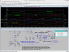
I created two core circuits exactly the same. The only difference between the two circuits is the voltage regulator choice.

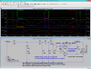
Each circuit can run efficiently on 4.5V to 5.5V. In my first circuit, I used a 7805CT regulator and in the second circuit, I used a LM2940CT regulator because I wanted a longer lasting battery and I heard the 7805CT can subtract alot of voltage from the input.

I have used the same capacitors around each regulator and in each test, the battery was the same (Brand new).

Why is it that with a 7805CT, I can get a 5.01V output, but with a LM2940CT the voltage output slowly decrements starting at 2.5V?

And if LM2940CT is the wrong item, then what can I use in place of a 7805CT that has a smaller voltage drop?
 
What is the full part number of the LM2940CT? There should be a couple of digits at the end indicating the output voltage.
The LM2940CT is a low dropout regulator, but it won't be any more efficient than a 7805 if they both have the same input voltage. For a LM2940CT you can supposedly feed it an input that is only 1 volt higher than the regulated output. I forget what the standard 7805 requires, but IIRC it's a couple of volts or more. But if you feed them the same input voltage, they'll both drop the same amount and waste the same amount of power.
 
I wonder if there is something the 7805CT can handle that the LM2940CT can't handle. After all, I'll be powering an LCD and 25 3-color LEDs. two of the 3 colors in the LEDs are driven by a 10K resistor and the other color driven by a 2K resistor. the LCD backlight is driven by a 10 ohm resistor and the LCD character brightness is controlled by a 2K resistor. I wonder if theres some kind of "tax" that these regulators experience. For example, I wonder if they lie about their maximum current capability
 
More questions:

What is the voltage of the battery that you're feeding them from?
Do the regulators get warm? hot?
What value capacitors are you using on the input and output of the regulators?
How close are the capacitors physically located to the regulators?

Are you saying that the output voltage of the LM2940 never goes above 2.5 volts?
 
What is the voltage of the battery that you're feeding them from?
9VDC (a square battery). I also hooked up a 1mF capacitor in parallel with the battery in all my tests to keep the voltage as stable as possible.

Do the regulators get warm? hot?
I didn't notice any of that, although I can understand if the 7805 gets warm over a 9V input but the circuit still works with it, just not with an LM2940.

What value capacitors are you using on the input and output of the regulators?
22uF (with 50V rating) for everything except that in the LM2940 setup I am using 100uF (with 16V rating) capacitor for the output. All capacitors are electrolytic.

How close are the capacitors physically located to the regulators?
For the new design, the input capacitor pin is 16.51mm away from the regulator pin and the width of the positive input track is at least 0.91mm. The output capacitor pin is 21.59mm away from the output regulator pin. The output track (circuit VCC) thickness is 1.78mm
I use a ground plane on my board.

Are you saying that the output voltage of the LM2940 never goes above 2.5 volts?
It probably would if I just stick in the battery and measure within 1/2 a second. When I plug in the working parts to the circuit (especially the LCD), it looks as if the circuit is continuously dying, and within seconds, the whole LCD screen goes off. I don't experience this with the 7805CT.

I double checked my board and haven't noticed any short-circuits or anything.
 
Try 0.1 µF capacitors on the input and output. The high frequency impedance of electrolytic capacitors may be causing a problem, You won't get that with the 0.1µF ceramic or film caps. With the electrolytics, you may be getting oscillation which could be causing the output problems. It is normal to use electrolytics on the input side if you're feeding the regulator from a rectified AC supply, but since you're using a battery, you don't need to filter out any ripple, and so the electrolytic is unnecessary there too.
 
What about my IC de-coupling? I mean in both circuits, I use 0.047uF caps to connect to each IC's VCC and ground. Could I get away with 0.047uF ceramic caps for the regulator? I don't have 0.1uF, but I own at least 200 0.047uF.

Would tantalum caps work or would they have the same impedance problems? I have a couple of them at 4.7uF.
 
Now I do have two holes left in my board for another input capacitor to go in parallel with the one already soldered on but I probably should replace the caps with 4.7uF tantanlum or 0.047uF ceramic.
 
I begin to wonder if tantalum are also no good. I switched electrolytics around the regulator to 4.7uF tantalum and I get the exactly same devastating results. Other than wait until I can get a hold of 0.1uF ceramics or sucking up to only 7805's, is there anything else I can do to solve my issue?
 
Man, I think I'm gonna need glasses or something because as I was testing my entire board, it turned out that I shorted a connection to VCC. The short was so small that I needed a magnifying glass to see the details of it. It was a short from a pin header to a wire thats running between the same pin header and another pin header about 2.5mm apart.

Luckily that connection was able to accept VCC as input.

For now I'm using 7805CT and may attempt to retry the LM2940 later
 
maybe
 

Attachments

  • _Draft_CL-LDO_noise_simple-Chp~2-Ti.png
    _Draft_CL-LDO_noise_simple-Chp~2-Ti.png
    52.4 KB · Views: 125
The datasheet for the LM2490 and for most other low dropout voltage regulators says that the output capacitor value MUST be at least 22uF, have the ESR shown and mounted very close to the LM2490. If it is less then the regulator loses stability and oscillates, probably between 0V and 5V (then the average is 2.5V) and oscillation probably causes it to heat up and slowly drop its average output voltage. Capacitor datasheets might show their ESR.
 
Oops, I missed the requirement for 22µF on the output.
 
(((("weird")))) point here is the simulation showing no problems whether there is any output filter or not - even more weird is the phenomenon that is revealed by checking the I/O reversal ← actually this is all regular spice magic as the fast changing signals are not properly integrated by simulator and the component model substitute would likely represent the unsteady output nature of collector load regulators . . .
:eek: i want that "The end of the world" chip -- think of connecting input back to the output -- you don't have enough devices to power
 

Attachments

  • _Draft_CL-LDO_noise_simple-Chp~2-Ti-3.png
    _Draft_CL-LDO_noise_simple-Chp~2-Ti-3.png
    60.8 KB · Views: 131
Status
Not open for further replies.

Latest threads

New Articles From Microcontroller Tips

Back
Top