Electro Tech is an online community (with over 170,000 members) who enjoy talking about and building electronic circuits, projects and gadgets. To participate you need to register. Registration is free. Click here to register now.
Welcome to our site! Electro Tech is an online community (with over 170,000 members) who enjoy talking about and building electronic circuits, projects and gadgets. To participate you need to register. Registration is free. Click here to register now.
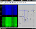
I've simulated a nice circuit for my purposes and find I can't breadboard it. I've checked continuity on all connections before powering, but I've failed to get it running.
There is no decoupling capacitor from the +ve supply to the 0v (Ground) line. Try a 10nF.
At a quick and dirty calculation, the oscillator frequency appears to be of the order of 2MHz.
Some breadboards can be a bit funny at high frequencies, although at 2MHz I think that you may "get away with it".
What frequency does the simulation say?
The simulation is saying 20kV on the secondary of the transformer, that is a bit much for any plug-in breadboard with 0.1" contact strips.
For 0.1" plug-in breadboards, 50vV would be a sensible maximum voltage.
I suggest that you build your circuit in an "ugly" or "Manhatten" style on a piece of circuit board with a continuous copper ground plane.
What made you think you could pulse such a high reverse voltage in both Vbe's? ( generally rated for Vbe=-5V max)
LTspice I believe does not simulate component failures from voltages or currents or power. Nor is it psychic to see your layout for stray wire inductance, and capacitance.
Anything less than 20 MHz is trivial on a breadboard . I measured ~35 ns risetime or ~ 0.35/0.035us = 100 MHz with no sparkplug ( wrong lib ref.) This means parasitic wire length and mutual coupling is more significant to be included in simulation and why 3D Manhatten style can work to reduce ESL ~ 0.8nH/mm
So either you have a wiring error or Vbe is broken (diode test) or parasitics with feedback are suppressing ( NFB) rather than reinforcing (PFB) oscillations or mutual and C coupling
I seriously doubt that a blocking-type oscillator would actually achieve a 2 Mhz output.
Blocking oscillators depend on the transformer core’s characteristics; namely saturation flux density.
And LTSpice, to my knowledge, doesn’t have a means to model saturation.
I am trying to make use of these 15KV coils on ebay.
Sure the circuit is stressed, but it should still work for a time.
As my last-ditch effort I put in some 1N750 zeners from the bases to ground and reduced the inductance of the primary to 80u with resistance of 410m ohms.
Haven't tried to breadboard yet, but I should make a circuit on copper board.
The website you linked shows the suggested drive circuit, and it is indeed a blocking oscillator. The core’s saturation characteristics play a role in its operation.
Why don’t you start with the provided circuit, rather than attempting to re-invent the wheel with a modified circuit that doesn’t include the most important characteristics?
Nigel beat me to a similar response. You don’t improve the wheel by making it square.
If you don’t like the original circuit, and the truth is that it is very crude and not very efficient, at least attempt to design a circuit understanding the essential theory behind it.
I have already mentioned a couple of times that core saturation characteristics play an essential role in a blocking oscillator. You asked for help. But the response I am only getting from you is pushing back on the fact.
This site uses cookies to help personalise content, tailor your experience and to keep you logged in if you register.
By continuing to use this site, you are consenting to our use of cookies.