Continue to Site

Welcome to our site!

Electro Tech is an online community (with over 170,000 members) who enjoy talking about and building electronic circuits, projects and gadgets. To participate you need to register. Registration is free. Click here to register now.

  • Welcome to our site! Electro Tech is an online community (with over 170,000 members) who enjoy talking about and building electronic circuits, projects and gadgets. To participate you need to register. Registration is free. Click here to register now.

why an inductor's time constant is L/R and not LR

Status
Not open for further replies.

PG1995

Active Member
Hi

Why is an inductor's time constant L/R and not LR?

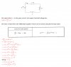
Let's say that Vin=10V, L=5H, and a variable R.

Case 1:
R=10Ω: L/R = 5/10 = 0.5s
Imax = V/R = 1A

Case 2:
R=5Ω: L/R = 5/5 = 1s
Imax = V/R= 2A

a rather crude conclusion:
In Case 1 time constant is less than that of Case 2 because maximum current of Case 1 is less than that of Case 2. It takes less time to reach fifth floor compared to tenth floor.

We can have a look on this formula B=μH=Ni/lc Wb/m^2 where "B" is magnetic flux density, "H" is magnetic field intensity, "N" is number of turns, "i" is current, and "lc" is length of core. For both given cases, everything is same except "i". In Case 2, the flux density is going to be twice compared to that of Case 1.

What I have said above is not complete or thorough but it would be enough to get the discussion started. Thank you.

Helpful links:
1: https://www.learnabout-electronics.org/ac_theory/dc_ccts45.php (animation)
2: **broken link removed** (read third paragraph on explanation of time constant)
3: https://www.falstad.com/circuit/e-induct.html (applet)
 
How can LR be a time constant? It does not have units of time.

To see the answer clearly, solve the first order system of a series LR circuit driven by a voltage source.
 
Time constants are relevant to changing voltages/currents associated with reactive components. In the case of a capacitor the reactance is inversely proportional to C, whereas for an inductor the reactance is directly proportional to L. Text books will give you equations relating R, L, C, V, Q and t for situations where a cap or inductor voltage or current changes.
Neither Case 1 nor Case 2 nor the formula involves a changing current or voltage, so I don't see their relevance.
 
Hi,

A very very reasonable question.

Simply put, the Henry can be converted into units of Ohm Seconds (ohms*sec), while
the Farad can be converted into units of Seconds per Ohm (sec/ohms).
We can immediately see the reciprocal relationship Alec was talking about. To get time, one must be multiplied by Ohms and the other must be divided by Ohms, hence either L/R or C*R.

The "time constant" is defined as the time it takes the response to get to an amplitude of 1-e^-1 (for a rising response).
This means that when we use a certain value of inductance and resistance we will see the amplitude increase as
1-e^(-t/(L/R))
but when we use a certain capacitance and resistance we see the response rise as:
1-e^(-t/(C*R))

So if we do several experiments we'll get those results, and so it is clear that one acts differently than the other.

I believe this is a very very reasonable question in part because the calculus relationships are more alike:
v=L*di/dt
i=C*dv/dt

and it almost makes sense to think that it should be tau=L*R as well as tau=C*R.

However, working those two equations together:
v*dt=L*di
i*dt=C*dv

If we choose dt such that dv=v*dt over smooth v we have:

v*dt=L*di
i*dt=C*v*dt

then:
v*dt=L*di
i*dt/C=v*dt

and now equate 1st and 2nd equations:

i*dt/C=L*di

Now we choose dt such that di=i*dt and we get:
1/C=L

or obviously:
L=1/C

So we see the nature of the inductor is different than the capacitor, even though they act in some similar ways.

Also inductance comes from a distance 'through' a medium, while capacitance comes from a distance 'across' a medium.

BTW, when you drive the series RC circuit with a voltage source the dual of that is a parallel RL circuit with a current source, so the two equations would be (RC=R*C):

VC=VC0*(1-e^(-t/RC))
and
IL=IL0*(1-e^(-t*R/L))
 
Last edited:
The questions itself is a bit confusing. "What is an inductor's time constant?". Are we talking about a real inductor with DC resistance R and self inductance L. In that case the question is meaningful. If the "R" in the question is an external resistance, and the inductor is assumed to be ideal, then the question should be "What is the time constant of a series LR circuit?".

I suspect the question is about the LR circuit, not the inductor itself. A real inductor does have it's own time constant L/R, but we generally hope that the value of R is small and another resistor will dominate in practice, so we usually don't need to worry about it for the time constant calculation itself (the inductor resistance might matter for losses and heating, however). But, for an LR circuit, the answer comes from studying the solution of the differential equation for the circuit. The solution is exponential in nature, and the time constant is a measure of the decay rate. Basically, time constants fall out of first order differential equations. Compare the first order differential equations of an RC circuit to an RL circuit and the answer is obvious.
 
Hi,

I've seen this question so many times now i automatically took it to mean either a R in series with L or an R in parallel with L. I could have been wrong i guess, but since he spelled out the L and the R and the fact that a time constant was involved i just assumed he mean the usual RL circuit.

Many people have asked about this on different forums over the years. It doesnt seem natural at first, but then after you look at the units and look into the behavior it becomes more natural. The inductor integrates voltage to get current, while the capacitor integrates current to get voltage, yet resistance is R=V/I so we can see that for C we get
t=C*V/I

and for L we get
t=L/(V/I)=L*I/V

and the defining equations again are:
V=L*di/dt
I=C*dv/dt

or:
V*dt=L*di
I*dt=C*dv

or:
dt=L*di/V
dt=C*dv/I

'Integrate' both sides we get:
t=L*I/V
t=C*V/I

and replace I/V with G and V/I with R:
t=L*G
t=C*R

and replace G with 1/R:
t=L/R
t=C*R

I just had to do this one more time :)
 
Thank you, everyone.

My special thanks to MrAl. MrAl, you did a superb job of helping me in terms of mathematics and considering my question a legitimate one.

I was talking about series LR circuit. It's somewhat surprising that Steve didn't 'understand' the question because he is one of those persons who could understand the anatomy of a question quicker than others, at least this has been true in my case many a time.

Let's start with a simple example. If someone is having problem understanding Ohm's law then we can give him the formula V=IR and tell him that this is the gist of everything. End of story and that won't be wrong from your point of view. Or, we can go like this. We can tell him that "R" has unit of V/A=Ω which translates to that if a potential difference of 1V is applied across a resistance "R" of 1Ω then it will let 1A current to pass through it. I believe that thinking along these lines would clear up things more and would provide one with both mathematical and intuitive understanding of Ohm's law.

On the other hand, I do agree that I'm someone who is always posed to committing offense of making things "simpler" in my mind in spite of having many shortcomings of my own. "Everything should be made as simple as possible, but not simpler." - Einstein

In case of series RC circuit, it can easily be visualized that if R is increased then during charging the capacitor would need more time to reach final voltage and likewise during discharging it will take more time to discharge to 0V because "R" restricts the flow of charges - larger "R" means 'more' restriction of charge flow. When I made my query I was simply trying to visualize series RL circuit along the same 'intuitive' lines without much success. Thanks a lot.

Best wishes
PG
 
PG, I did understand the question, but I was pointing out an ambiguity in your question.

Also, I too considered your question a legitimate one. I also believe my answers are legitimate. Please consider them and give them a chance to influence your ability to answer such questions, or to pose questions in a better formulation.
 
Last edited:
PG, I did understand the question, but I was pointing out an ambiguity in your question.

Also, I too considered your question a legitimate one. I also believe my answers are legitimate. Please consider them and give them a chance to influence your ability to answer such questions, or to pose questions in a better formulation.

Yes, your answer was a legitimate one. I would do what you tell me! Sometimes I could take time but I always try to follow others' advice and suggestions. This is my attempt. I used the formula. Did you want me to derive that formula too? Please let me know.Thank you.

Regards
PG
 

Attachments

  • rl_ckt_diff.jpg
    rl_ckt_diff.jpg
    147.6 KB · Views: 1,355
Notice how you have so much capability to analyze and derive solutions now. Consider where you were a few years ago. Because I know you have these abilities, I wanted to you to think in these terms.

So yes, basically that is it. And then you can do the same for the RC circuit. Actually, you don't even need to take it as far as you did, if you know the basics of a first order differential equation, which you know now. You know the solution to a first order equation with constant coefficients is an exponential type change, as you just derived. You should learn to recognize the form instantly whenever it occurs in your work, because it shows up in so many places. The same can be said for the second order system, although that one is more complicated.

For example, consider the magnetizing current in an induction motor, and how it evolves from the d-axis current which energized the flux in the rotor.
d Im/dt =-(R/L) * Im + (R/L) *Id, where R is the rotor resistance and L is the rotor inductance. In other words the rotor time constant is L/R. Notice the negative sign in front of the R/L which indicates stability because the pole is in the left side of the complex plane with Re(P)<0. Notice there is an input signal that drives the system, which in this case is Id.

So, for a series RC circuit driven by constant voltage source Vin, you would derive d Vc/dt = -(1/RC) * Vc + (1/RC) * Vin. The negative sign instantly tells you it is stable and the solution won't blow up. It's clear that Vin is the input that drives the system.

And, for a series RL circuit driven by a constant voltage source Vin, you would derive d I/dt = -(R/L) * I + (1/L) * Vin

Linear first order equations with constant coefficients, which are stable systems, always have this form. The pole locations are always obvious too because the Laplace transform can be done by inspection if you remember that derivatives are equivalent to multiplication by "s". The poles occur at s=-1/tau, where tau is the time constant, and the low pass filter transfer function form is always T=A * ( w/(s+w)), where w=1/tau, and A depends on the type of input that drives the system.

These are basic things that should be committed to memory. You should recognize them immediately, much the same way a sailor should know how to spot the north star.

Now let me give you a hint about a powerful trick to solving higher order systems. Consider a state space formulation. It actually looks like a first order system, except the object of the solution is a vector and not a variable. For a state space system you have dx/dt=A x + B u, where x and u are vectors and A and B are matrices. The x vector is the state or system variables and the u vector is the input variables. It is possible to solve such systems using the same basic solution you just used, but you have to be careful about the order of operations because the objects are vectors/matrices and not scalars. This is called the state transition matrix approach, and you can look it up in your books (e.g. p. 666 of Ogata). However, you recently saw an example of this when I derived the solution for a Buck converter using this method. I was then able to write a simple Matlab program to simulate buck converters in about 15 minutes, using the solution. In other words, think of the simple first order system you are asking about as a prototype for more advanced and complicated systems.

EDIT: check the sign of the exponential in your solution. You should get 1-exp(t/tau) type solutions.
 
Last edited:
Hello,

Yes not to nit pick but charging solutions usually come out with a subtractive exponential, and for this case it is because when applying the initial condition of i(0)=0 we could get a negative value for c, which of couse leads to 1-e^(-at) instead of 1+e^-at.

The motivation for your question is even more clear now since your more recent posts. Often it is not enough to simply state "that's just the way it is" because that doesnt satisfy our curiosity sometimes. And bringing up L/R vs C*R begs the question why one should be divided while the other multiplied.
 
Mr Al,

I don't think it is nit-picking at all to point out that the 1-exp solution is the important one to understand. This shape shows up all the time when we look at scopes and response plots of first order systems.

It doesn't bother me that PG made a derivation mistake. I make such mistakes all the time, which is why I always double check my work when doing engineering (but not here in the forum, where I show many mistakes :) ), and as I get older, I now triple and quadruple check, both because I'm becoming more fallible with age and because I'm more experienced and have seen the consequences of mistakes that slip through.

But, I'm a little surprised that PG didn't notice himself because the 1-exp shape is so well known and it shows up in so many places. But, I know PG has a mountain of work he is doing on his project, so actually, I should not be surprised.

Looking at his work, I feel the real problem is that formula for solving first order PDEs that he remembers from his previous coursework. I never liked that formula because it is confusing. There are no clear indications of where the integral means "antiderivative" and where it means definite integration. The variable x is used for integration in 3 places, and no limits are provided. I think the state transition matrix approach is better when the PDE has constant coefficients, and that approach works for any order linear system, not just the first order case. Using that formalism, the initial conditions are explicitly clear and the limits of integration are explicitly clear.
 
Hi,

I like the state variable approach too and sometimes really prefer that over say a frequency domain approach.
I do also realize however that there are a lot of ways of approaching these circuits so i was thinking of writing a book, "101 ways to analyze a circuit" <chuckle>. Sounds funny, and it is, but i bet we could actually do it :)
I think the different ways bring out different points about the way the circuits work.
 
Hi

That day I didn't put my query clearly so let's give it another try.

In a series RC circuit, increasing the value of R results in a larger time constant. A capacitor takes 5 time constants for its complete charging or discharging as shown here. Why does increasing the value of R results in larger value of time constant? Having a larger resistor means that flow of charges is restricted more and hence it takes longer for the capacitor to get fully charged or discharged. Likewise, having a larger capacitor would require more charge to get fully charged/discharged. Therefore, τ ∝ R and τ ∝ C.

I was making query about the constant L/R from similar perspective. In other words, τ ∝ L and τ ∝ 1/R. Why is time constant, τ, inversely proportional to resistance R? Thanks.

Regards
PG
 

Attachments

  • time_constant.gif
    time_constant.gif
    11.3 KB · Views: 10,170
The bigger the resistance is, the smaller the current needed to use up the available supply voltage. The resistor voltage Vr equals IR. If the inductor is ideal, then R is zero and there is no limit to the current that can (theoretically) exist in the coil. Hence it would take an infinite amount of time for the current to max-out. The rate of change of current also is affected by the available voltage on the coil. If the resistor uses the voltage up, then less voltage is on the coil and the rate of change of current decreases. Once the resistor has used all the voltage, the rate of change of current is zero, because the coil no longer has voltage drop.
 
Thank you, Steve.

When a series RL circuit is turned on, the inductor behaves like a huge resistance for an infinitesimal amount of time. Then, gradually the current starts flowing. For every infinitesimal increase in the value of current, the resistor 'steals' some of voltage away from the inductor. It means that if you double the size of resistor, say from 5Ω to 10Ω, then this process of 'stealing' the voltage away would be more aggressive because it takes more pressure to push 100 charges thru a 10Ω resistor than thru a 5Ω resistor.

Voltage across inductor = L*di/dt

The more the voltage across inductor gets stolen away for every infinitesimal increase in value of current, the sooner the current approaches its peak value and hence relatively shorter time constant. In other words, the rate of change of current decreases at a faster rate. Thanks.
 
Status
Not open for further replies.

Latest threads

New Articles From Microcontroller Tips

Back
Top