Continue to Site

Welcome to our site!

Electro Tech is an online community (with over 170,000 members) who enjoy talking about and building electronic circuits, projects and gadgets. To participate you need to register. Registration is free. Click here to register now.

  • Welcome to our site! Electro Tech is an online community (with over 170,000 members) who enjoy talking about and building electronic circuits, projects and gadgets. To participate you need to register. Registration is free. Click here to register now.

Which relay to be used? DC or AC?

Status
Not open for further replies.
bananasiong said:
how to calculate that? what is the output if 15V is supplied?
You can't read the datasheet and make a simple Ohm's Law calculation?
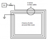
The output will go to 12.5V with a 15V supply and 200mA of load. Therefore the total load resistance = 12.5V/200mA= 62.5 ohms. If the wire's resistance is 0.5 ohms then a 62 ohm resistor could be used in series with it. The power rating of the resistor should be 2.5W.

f i drive it in maximum (200mA), like what u have mentioned, the high power will cause heat. will it burn the resistor or wire?
A 2.5W resistor will get hot but still survive. A small resistor will burn out. Extremely thin wire will burn out.
 

Attachments

  • lm555_167.png
    lm555_167.png
    10.9 KB · Views: 161
audioguru said:
You can't read the datasheet and make a simple ohm's Law calculation?

sorry about that, i've read the data sheet, but i get no point from that. seriously i don't know how to find the correct info.

A 2.5W resistor will get hot but still survive. A small resistor will burn out. Extremely thin wire will burn out.

2.5W resistor is the normal type or the bigger one? is it depends on the color at the last line of the resistor? extremely thin wire will burn out, single core wire is also known as thin?
 
The datasheet for an electronic part tells you exactly how the part is guaranteed to perform. You should learn how to read a datasheet.

Resistors are rated for max power. Their size determines how much power they can dissipate.

There is a wire guage vs max current table. You should learn it.
 
bananasiong said:
audioguru said:
Haven't you learned about power???
Voltage times current equals power. Power in an electronic device creates heat. If you have a 12V supply and the output voltage of the 555 is 9.5V, then 9.5V x 200mA= 1.9 Watts which is a lot of heat for a small resistor.

sorry, sometimes i can't differentiate well them. 1.5 watt is a lot of heat? then how many watt isn't? so i have to remain the 100R and to limit the current, the 200mA is to large.

CAT 5 cable is common here and it is cheap. Use multiple wires from a telephone cable instead.

the CAT 5 cable can be found in electronics shop or computer shop?

It's called network cable, ethernet cable, LAN cable.... if you're in KL i'm sure you can find it at Imbi/Lowyat or any of the other small shops around.
 
http://www.thelearningpit.com/elec/tools/tables/Wire_table.htm

is this table? but i'm not sure the diameter of the wire i'm using. mayb i can try to ask around. i think i will remain the 100R for safety first.

instead of using the CAT 5 cable, can i just connect a few long single core wire in parallel to increase the magnectic field?

It's called network cable, ethernet cable, LAN cable.... if you're in KL i'm sure you can find it at Imbi/Lowyat or any of the other small shops around.
thanks, but i'm not in KL.
 
bananasiong said:
instead of using the CAT 5 cable, can i just connect a few long single core wire in parallel to increase the magnectic field?
The wires must be in series in order to make a loop that has multiple turns.
 
audioguru said:
bananasiong said:
instead of using the CAT 5 cable, can i just connect a few long single core wire in parallel to increase the magnectic field?
The wires must be in series in order to make a loop that has multiple turns.

i thought the CAT has many wires inside, and connect them to the output of 555 as shown in figure below :roll:
 

Attachments

  • 555_267.jpg
    555_267.jpg
    9.8 KB · Views: 188
bananasiong said:
i thought the CAT has many wires inside, and connect them to the output of 555 as shown in figure below :roll:

No, that wouldn't help, wire it so they are all in series, effectively giving a number of turns to the coil.
 
Nigel Goodwin said:
No, that wouldn't help, wire it so they are all in series, effectively giving a number of turns to the coil.

sorry, i really don't get it. if i connect them in series, that means there is only one wire connect from the output to the GND. can u show me in picture?
 
Connect the wires in the cable in series, then the magnetic field from the cable is increased.
 

Attachments

  • loop_of_wires.png
    loop_of_wires.png
    8.2 KB · Views: 158
audioguru said:
Connect the wires in the cable in series, then the magnetic field from the cable is increased.

thanks!! i understand already. :wink: so i can use only the single core wire to turn for a few round, right?
sorry for my poor understanding.
 
bananasiong said:
audioguru said:
Connect the wires in the cable in series, then the magnetic field from the cable is increased.

thanks!! i understand already. :wink: so i can use only the single core wire to turn for a few round, right?
sorry for my poor understanding.
yes u can ..but.. as already suggested it would be better to use the cat5 since it has many lines inside (just connect then to become a loop) , rather than using multiple loops of single core
 
akg said:
yes u can ..but.. as already suggested it would be better to use the cat5 since it has many lines inside (just connect then to become a loop) , rather than using multiple loops of single core
okay, thanks i will try to find the CAT 5 cable. if i can't find it, i will use my own way :wink:

the CAT 5 can drive how many watt?
 
bananasiong said:
okay, thanks i will try to find the CAT 5 cable. if i can't find it, i will use my own way :wink:

the CAT 5 can drive how many watt?
Telephone cable is available with many wires, use it if you can't find CAT 5 cable.
Wire is rated in AMPS, not in WATTS. 200mA is very low and just about any reasonable wire size can pass it.
 
oh.. i found the CAT5 already, actually is CAT6 (that's what available at my place). can i connect as shown in below? just a little bit different.
 

Attachments

  • 555.PNG
    555.PNG
    2.6 KB · Views: 153
bananasiong said:
oh.. i found the CAT5 already, actually is CAT6 (that's what available at my place). can i connect as shown in below? just a little bit different.

NO! - that will cancel itself out, wire it as you've already been shown!.
 
Nigel Goodwin said:
NO! - that will cancel itself out, wire it as you've already been shown!.
oh! luckily u told me, otherwise i will wire them like what i thought can be done. thanks! :D
 
Your sketch is missing the current-limiting resistor that should be in series with the loop of wire. The 555 will melt without the resistor because its max current rating is only 200mA, and a loop of wire could be a dead short to it.
 
audioguru said:
Your sketch is missing the current-limiting resistor that should be in series with the loop of wire. The 555 will melt without the resistor because its max current rating is only 200mA, and a loop of wire could be a dead short to it.
yup, i have forgotten to include it.. hehe.
the 555 timer will melt!?!? i didn't know that, it is so serious!! but i will remain the 100R to limit the current, in case the wire cannot support it. since the multiple loop can increase the electromagnetic field :D
 
my explaination

hi all,
i'm going to do presentation with this circuit 2 weeks later. if anything goes wrong, correct me ok?

The 555 timer produces a 10kHz(approximately) squarewave output at pin 3 with the combination of R1, R2 and C1. The 'antenna' will produce electromagnetic field on and off in 10kHz.

the resonant frequency of the tank circuit is 10kHz. the 100K resistor creates a gain of a few hundred thousand which is so high that it probably amplifies its own noise and any noise that is around. It might even oscillate.
If a 0.1uF capacitor is added to ground at pin 3 then it won't oscillate. When the signal is received then the output of the receiver should alternate between 0V and Vcc at the frequency of the input. With a 5V supply then the output's min current of only 6mA should be able to saturate good with 5mA from a 1k load.


are these correct? i copied them from urs explaination. is there anything to be explained with this circuit?

edit:
1. what is the purpose of the 0.01uF capacitor from pin5 to GND of the 555?
2. why the 0.1uF capacitor from pin3 to GND at the LM393 can stop it to amplify other noise and its own noise and stop oscilating?
3. what's the different between a comparator and operational amplifier? can a comparator be an op-amp and vice versa?

thanks for helping..
 

Attachments

  • a.PNG
    a.PNG
    18.5 KB · Views: 820
Last edited:
Status
Not open for further replies.

New Articles From Microcontroller Tips

Back
Top