Continue to Site

Welcome to our site!

Electro Tech is an online community (with over 170,000 members) who enjoy talking about and building electronic circuits, projects and gadgets. To participate you need to register. Registration is free. Click here to register now.

  • Welcome to our site! Electro Tech is an online community (with over 170,000 members) who enjoy talking about and building electronic circuits, projects and gadgets. To participate you need to register. Registration is free. Click here to register now.

where have I gon wrong on

Status
Not open for further replies.

Gregory

Member
I was mislead of the requirements for the 7 segement display that I posted earley.
The requirement of the display is to show 34
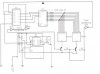
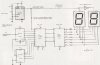
I have a attachement to this post of the circuit digram could it be explained to me where I am going wrong on this circuit.
 

Attachments

  • 34_display_counter.jpg
    34_display_counter.jpg
    25.6 KB · Views: 312
What is the exact requirement? A counter up to 34? Or need on the display only 34? (in this case need only resistors for desired LED segments...)
 

Attachments

  • 34_display_counter.gif
    34_display_counter.gif
    8.3 KB · Views: 299
this can be reset when it hits 35.

Using AND gates, by placing on the ABCD output of the counters. 1's counter, use output A and C into the input of a AND gate IC, plug the output of the AND into another input of the AND gate, on the output of 10's counter take the output A and B to a separate input Gate take that output and plug it into the input that the combind output AC 1's counter is going into.

I know kind of hard to understand even for me.

Simple:

1's counter out AC into input AND> take output to next AND gate over
10's counter out AB into opposite side input AND> take output to the front second Gate where AC out is going into.

PINs for working a AND reset:
1's) A pin 1, C pin 2, AB output pin 3>to input pin 4
10's) A pin 10, B pin 9, output pin 8>to input pin 5
Take pin 6 and wire it into the counters CLR pin 14 without ground. The AND gate IC should tie it low enough for logic to keep running untill both AND's are activated.
 

Attachments

  • scan0002ab.jpg
    scan0002ab.jpg
    492.6 KB · Views: 264
Status
Not open for further replies.

Latest threads

New Articles From Microcontroller Tips

Back
Top