Continue to Site

Welcome to our site!

Electro Tech is an online community (with over 170,000 members) who enjoy talking about and building electronic circuits, projects and gadgets. To participate you need to register. Registration is free. Click here to register now.

  • Welcome to our site! Electro Tech is an online community (with over 170,000 members) who enjoy talking about and building electronic circuits, projects and gadgets. To participate you need to register. Registration is free. Click here to register now.

Wheel of FORTUNE HELP

Status
Not open for further replies.

garage100

New Member
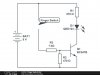
The above circuit was built on a matrix without transistors ( 2n3904 ) .
The Circuit worked fine until the transition to the solder board which included all the parts. I checked the board three times .
The Circuit is taken from https://www.talkingelectronics.com/EM/KitsForSale/WheelOfFortune.html
I wanted to restrict the movement of four LEDs , so I shorted leg 10 to 15 in 4017 .
In addition I wanted to control the timing and changed the capacitor connected to 555 to 100U and added variable resistors.
The problems :
1. After switching to a solder board the rotation stopped at the same group of LEDs repeatedly. the randomality has disappeared . Is there a mistake in a circuit attached ? Why doesn't it stops with a another group of leds in every rotation round?
2 . The LEDs are piranha 5 mm 3v . When the group of blue LEDs turn on, the LED connected to the resistor(150) is flashing. Is the LED broken or is there a problem in 2n3904 ?

I'm really desperate
please help
yoav
CIRCUIT.jpg
 
The two LEDs that you have in series in each group will be pulling down the supply voltage as they don't have a current limiting resistor. There is no isolation so variations in voltage will affect the oscillator.
 
You don't indicate your DC supply voltage but as Diver300 has pointed out you need a series resistor to limit the current to your LEDs. You would be better with your 3 LEDs in series with the appropriate resistor, DC supply voltage permitting.
 
Your DC supply at 9V is a problem. Can you increase to 12V?

Three leds in series will drop 9V according to your specification which leaves no leeway for a series resistance or a control transistor.
 
I can't increase the battery to 12v.
What can be done?
Perhaps connect 3 LEDs in parallel with 100 ohm resistor?
 
Your circuit is a considerable variation of the original design.

What is your expected action of the circuit you have created?
 
I can't increase the battery to 12v.
What can be done?
Perhaps connect 3 LEDs in parallel with 100 ohm resistor?

You can but LED's in parallel are never a good idea due to variations in their specifications. Ideally you need each LED to behave exactly the same and have the same voltage drop for example but in the real world this doesn't happen and differences can cause one diode to pull more current than the others and reduce their life.

Can you reduce the LED's to two in each leg? A series resistor of around 100R should then be OK.
 
Your circuit is a considerable variation of the original design.

What is your expected action of the circuit you have created?

My expected action will be to press the push button and get four group of LEDs cycling for 5-6 seconds. Each time One of the 3 LEDs stays on (randomly). Each group has a different color.
 
You can but LED's in parallel are never a good idea due to variations in their specifications. Ideally you need each LED to behave exactly the same and have the same voltage drop for example but in the real world this doesn't happen and differences can cause one diode to pull more current than the others and reduce their life.

Can you reduce the LED's to two in each leg? A series resistor of around 100R should then be OK.

Thanks you for your time.
I need the 3 LEDs to light an acrylic sheet. Each led has 110 degree beam. The 3 LEDs are the only way to get a full cover.
 
The Cmos counter IC has a limited amount of output current. It is shown in the datasheet from Texas Instruments for their CD4017 which is the same as the Philips HEF4017 . The output current of any CD4xxx Cmos logic IC is the same, but some have the minimum output current which is half of the typical current.

With a 10V supply the typical output current to two 3V LEDs in series without a current-limiting resistor is 13mA. Then the output transistor in the IC has a voltage across it that is (10V - 6V=) 4V and heats with (13mA x 4V=) 52mW. The maximum allowed heating of an output transistor in the IC is 100mW so it is fine with no current-limiting resistor and the battery will be fine if it is a new alkaline name-brand battery. If you add a third LED with a 470 ohm series resistor then the two LEDs and the one LED will share the total current which will be about 6mA each (not bright).
The LEDs will slowly dim as the battery voltage runs down.

The circuit will work better if the 9V supply has a 100uF to 470uF capacitor across it.
 
You are forcing a reset of the 4017 on the 5th pulse from the 555.

What pin is connected to the LED(s) that remain on (according to your post it is always the same set) each time you press and release the push button?

What is the voltage across the battery when the circuit "locks"?

In your schematic, the wipers of the pots are not connected (perhaps merely an error). In either case, does the particular set of LEDs that remain on differ if you adjust the 500k pot in the trigger circuit?
 
You are forcing a reset of the 4017 on the 5th pulse from the 555.
Perfect. Then it counts from one to four then starts again at one.

I think the supply voltage is bouncing up and down because it is missing an important supply bypass capacitor and because maybe the battery is not new.
 
Thank you all for your replays.
I arranged the LEDs with 100 ohm resistors and now it works.
How can I replace to push button with the finger touch circuit?
 

Attachments

  • image.jpg
    image.jpg
    27.8 KB · Views: 174
Status
Not open for further replies.

Latest threads

New Articles From Microcontroller Tips

Back
Top