You guys probably know that I am now retired. Back in the mid-70s, I worked for Consolidated Video Systems in Mountain View, CA . We **broken link removed** for video tape recorders. I had been hired to do A/D and D/A converter design, along with other miscellaneous analog circuit design tasks.
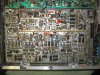
My crowning achievement was the ADC for the CVS 520. It was a 9 bit ADC, sampling at 14.3 megasamples/sec. It was autoaligning, for the most part. It only had 6 pots, and the alignment techs loved it.
You might say that's a lot of parts for an A/D. You can buy a comparable one today on a chip for a few bucks. When I designed this, there was a total of one A/D IC available. It was made by TRW, was in a 64 pin DIP, cost $600 (!), dissipated 7 watts, and required that you epoxy a heat sink on it and blow forced air over it. My board was considerably bigger, and probably drew more power, but it was only $180 out the door, including testing and alignment. It had no exotic parts in it. Differential gain and phase were outstanding, and, due to the autoalignment, it didn't drift out of alignment.
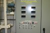
I bought this used CVS 520 on Ebay in a fit of nostalgia several years ago for about $100. They had sold for $15k originally.
Oh, I should mention: No simulation, and all schematics were drawn by hand, on a drafting table.


")