karenhornby
New Member
Has anyone got any suggestions for a program that will ptint out a circuit diagram on to laminate for etching?
I've tried simple things like Crocodile Clips but once you manually lay out the components it gets rid of the lot when you try and save it.. no use!
I've tried Express PCB but I cant figure out how to work it and it dont have the components I need.
I've tried Visio from office 2007 but have no clue how to get that working
I've tried the free version of autocad but way too complicated
What I need is a "simple?" program that has the following components in its library
TIP120
NE555
1N4001
DS1620
LM7805
and the usual resistors and capacitors etc.
I need a decent track layout program so I can actually check what I've done so far.
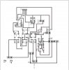
I've enclosed my circuit diagram here so people can see what I mean, and I've also enclosed a scan of the track layout I managed to do with crocodile clips before the stupid program closed and I lost it.
So if anyone has any suggestions to a program thats simple for a "bimbo" to use? please let me know, thanks")
On a 2nd note, does anyone with any knowledge of PIC programming fancy helping out?
I've got this idea but I know nothing about writing programs for PIC chips and to be honest just for one application its not worth it.
What I want to do is have a pic chip that controls a 2 line LCD readout, with the 2nd line always displaying "OUTSIDE TEMP (actual temperature) ºC and reading the temp by another DS1620 or maybe an LM35
the 1st line of the display would read either the words DIESEL VEG-OIL or the word PURGING depending on which led on the above circuit is active at the time
for example
if the GREEN LED is active it would display the word DIESEL
if the BLUE LED was active it would display the word VEG-OIL
if the RED LED was active it would display the word PURGING
If anyone knows a simple circuit diagram for achieving that (along with the code to program the pic with) you'll have a very happy "bimbo"
OH if it's possible to incorporate a timing circuit inside the PIC chip that will count to 30 seconds to replace the S1 in the circuit (momentary push to make non latching switch) and associated 555 circuitry it would cut down the component count massively. but its not essential as the 555 circuit works, it would just make the project neater.
This is for my own use, in my own car (as you may have guessed its a circuit for auto switchover to vegetable oil from diesel once the preset temps in the 2 X DA162's have been reached) and wont be used commercially in any way.
I've tried simple things like Crocodile Clips but once you manually lay out the components it gets rid of the lot when you try and save it.. no use!
I've tried Express PCB but I cant figure out how to work it and it dont have the components I need.
I've tried Visio from office 2007 but have no clue how to get that working
I've tried the free version of autocad but way too complicated
What I need is a "simple?" program that has the following components in its library
TIP120
NE555
1N4001
DS1620
LM7805
and the usual resistors and capacitors etc.
I need a decent track layout program so I can actually check what I've done so far.
I've enclosed my circuit diagram here so people can see what I mean, and I've also enclosed a scan of the track layout I managed to do with crocodile clips before the stupid program closed and I lost it.
So if anyone has any suggestions to a program thats simple for a "bimbo" to use? please let me know, thanks
On a 2nd note, does anyone with any knowledge of PIC programming fancy helping out?
I've got this idea but I know nothing about writing programs for PIC chips and to be honest just for one application its not worth it.
What I want to do is have a pic chip that controls a 2 line LCD readout, with the 2nd line always displaying "OUTSIDE TEMP (actual temperature) ºC and reading the temp by another DS1620 or maybe an LM35
the 1st line of the display would read either the words DIESEL VEG-OIL or the word PURGING depending on which led on the above circuit is active at the time
for example
if the GREEN LED is active it would display the word DIESEL
if the BLUE LED was active it would display the word VEG-OIL
if the RED LED was active it would display the word PURGING
If anyone knows a simple circuit diagram for achieving that (along with the code to program the pic with) you'll have a very happy "bimbo"
OH if it's possible to incorporate a timing circuit inside the PIC chip that will count to 30 seconds to replace the S1 in the circuit (momentary push to make non latching switch) and associated 555 circuitry it would cut down the component count massively. but its not essential as the 555 circuit works, it would just make the project neater.
This is for my own use, in my own car (as you may have guessed its a circuit for auto switchover to vegetable oil from diesel once the preset temps in the 2 X DA162's have been reached) and wont be used commercially in any way.
Attachments
Last edited:
