Hi, All
i'm trying to buid a flip flop which supposed to flash 12 volt Lamp one and another.
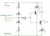
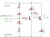
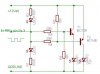
Managed to hook up IC 555 as an astable multivibrator, it works fine with leds. the leds ( D1 and D2 ) are flashing as planned. But when i connect two power transistor to increase the current which the lamps will consume, lamp1 lits continuosly ( not flashing ) and lamp2 is not light up at all.
I have tried to light up leds instead of lamps by using small ( NPN, and PNP ) BC type transistor, the result was the same.
Can anybody tell me what is wrong with these transistors that not obeying my orders
i'm trying to buid a flip flop which supposed to flash 12 volt Lamp one and another.
Managed to hook up IC 555 as an astable multivibrator, it works fine with leds. the leds ( D1 and D2 ) are flashing as planned. But when i connect two power transistor to increase the current which the lamps will consume, lamp1 lits continuosly ( not flashing ) and lamp2 is not light up at all.
I have tried to light up leds instead of lamps by using small ( NPN, and PNP ) BC type transistor, the result was the same.
Can anybody tell me what is wrong with these transistors that not obeying my orders
")
 be more OPTIMISTIC. the more things you built the faster you will learn to do them. i remember doing a simple oscilator, wich i used to blink 2 leds and it took me 2 days, but now i can do it in 20-30 minutes.