Continue to Site

Welcome to our site!

Electro Tech is an online community (with over 170,000 members) who enjoy talking about and building electronic circuits, projects and gadgets. To participate you need to register. Registration is free. Click here to register now.

  • Welcome to our site! Electro Tech is an online community (with over 170,000 members) who enjoy talking about and building electronic circuits, projects and gadgets. To participate you need to register. Registration is free. Click here to register now.

what is this the symbol for? Looks like some kind of transistor?

Status
Not open for further replies.

Triode

Well-Known Member
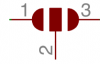
From usage it looks like it's an isolator or a transistor, but I can't find what exactly it means on any chart of component symbols. This is a DMX sheild. Its interesting that two of them are being used with both outputs, apparently to go to two different voltage levels? One says arduino TX and RX and the other says VTX and VRX. But the pair on the left don't split, they go to an enable and one ties to ground while the other ties to vcc. These are probably really common protection circuits but I'm not sure what to look up to check them. I figure I could learn from reading about it.

Thanks!

1551991101055.png
1551991474018.png
 

Attachments

  • 1551991412926.png
    1551991412926.png
    6.9 KB · Views: 110
  • 1551991423481.png
    1551991423481.png
    6.9 KB · Views: 113
Those appear to be solder pads for bridging with solder to set default conditions.
These bridging solder pads are often pads very close to each other on the circuit board, to allow easy bridging with a simple blob of solder.
 
Yes, looks like you can use the default Arduino Rx/Tx pins but you can also use the alternate pins.
 
On this page:
**broken link removed**
there is a zoomed-in section of the PCB and you can see that the pads are populated with a zero Ohm resistor.
 
Agree they're solder pads, however, when I used one in the past it had a default connection. If you imagine the connection at 1 continuing to the middle pad so pins 1 and 2 are connected but can easily be disconnected with a knife or screwdriver.

Mike
 
Agree they're solder pads, however, when I used one in the past it had a default connection. If you imagine the connection at 1 continuing to the middle pad so pins 1 and 2 are connected but can easily be disconnected with a knife or screwdriver.

Mike

The default ARE connected with 0R resistors as the default. They should be clipped and new 0R resistors added to the alternat pad and the center pad.
 
The ones I used were in the days when smt wasn't normal for amateurs. They just had a thin track bridging the default pads.

Mike.
 
The ones I used were in the days when smt wasn't normal for amateurs. They just had a thin track bridging the default pads.

Mike.

The ones I had in the day were through-hole R0 resistors and even easier to clip than an SMT resistor. Three black bands on the through-hole from some brands - others had one black band.
 
Ah, I can see that on the board in the picture now that you point it out. That makes sense to me. I had seen the jumper symbol but not the 3 way version of it. I thought maybe it was some kind of device letting the signal through at two different voltage levels. But simply picking between the two makes sense.
 
If you look more closely at the schematic, it shows the zero Ohm resistors at R2, R4, R5 & R6 in the default positions across pads 1 + 2.
 
Status
Not open for further replies.

Latest threads

New Articles From Microcontroller Tips

Back
Top