Continue to Site

Welcome to our site!

Electro Tech is an online community (with over 170,000 members) who enjoy talking about and building electronic circuits, projects and gadgets. To participate you need to register. Registration is free. Click here to register now.

  • Welcome to our site! Electro Tech is an online community (with over 170,000 members) who enjoy talking about and building electronic circuits, projects and gadgets. To participate you need to register. Registration is free. Click here to register now.

What is this connector called? Nokia 240x320 pixel RGB TFT LCD connector

Status
Not open for further replies.

hantto

Member
Hi!

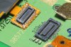
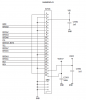
I've got a couple of old nokias around with perfectly good LCDs. I think I have found the driver chips and pinouts of the LCDs. Now I only need the connector to be able to try it out. I tought it might be somekind of Hirose connector, but I cant seem to find a 24 pin version of it. Attached is a picture of the connector. It is the right-hand side i'm interested in. I also attached the pinout and driver datasheet for those who are interested. The controller seems to be LDS285. This display is atleast in the Nokia 6555 and 3120 classic. The 6555 has two displays, which seem to have the same interface.

Thank you.
 

Attachments

  • nokia_lcd_connector.JPG
    nokia_lcd_connector.JPG
    331.6 KB · Views: 749
  • pinout.png
    pinout.png
    30.4 KB · Views: 2,005
  • LDS285.pdf
    2.7 MB · Views: 1,096
It seems to be a hirose-type connector nevertheless. The closest mathces were DF30 DF37 DF40 and FX12, but still not correct.

Does anybody have experience with these? Or as anybody been successful in soldering leads directly to pins with 0.4mm spacing?
 
Thank you for the reply. That Molex connector indeed looks very similiar, even tough not exactly the same, might even be compatible?

Further investigating I stumbled on the site http://rossum.posterous.com/screen-play-lots-of-other-screens-for-microco where in the comments somebody gave this link http://www.jst.co.uk/productSeries.php?pid=12210&cat=17, which is EXACTLY the right connector (24R-JANK-GSAN-TF). Woo!

Now I "only" need to find a distributor :) Digikeys minimum order is 4000 pieces.

Thanks again.
 
Yes, I found the shop. I tried registering for samples too, but they only seemed to ship to the USA and a couple of other countries. I found that JST have several websites depending on the geographical locations. Turns out that the Belgian site ships samples to Finland. I've now placed an order.

Some JSTs websites are not too "professional". So it took a while while navigatng them. The shop seemed a bit "unfinished" too.

Thanks, hantto
 
A little follow-up:

I received my samples within 4 days of requesting them. The JST samples representative was very friendly. I made a PCB at home with the needed 0.4mm pin pitch. I was a bit worried that the result would not be good enough, because my printer already seemed to have some problems printing 0.2mm wide traces. But it turned out to be "quite-ok", I was surprised.

I attached some close-ups of the connector and soldering. The hardest part was to center the part, and as you can see, it is off by maybe 0.05mm, but that is good enough :) My strategy was to apply solder paste onto the traces, then center the part, and finally use the soldering iron to melt solder onto the traces. The solder then flowed up to the pinns because of the solder paste.

It will probably take some time before I get the time to play with the LCD itself.
 
And the next follow-up!

I have got the LCDs working. It was actually quite easy once the circuitboard was made. The Nokia 6555 has two LCDs, one 320x240 16M colors and one 128 x 160 pixel with 262k colors. Both have the same electrical interface, except for the backligth leds and The P_select pin.

I broke my LED driver when I connected the smaller LCD to my circuit. After a little measuring, I found that the pins for the second led pair were grounded. I soldered off the boost converter diode and connected the small LCD up. Even though the backlight was off, I could see it reseting and clearing the display, so it is safe to say that the LCD's interface is identical. Ofcourse, all of this is quite evident if you look at the nokia 6555 schematic.

I made my circuit with a PIC18F25k20, mostly because that was the only chip I had that still worked with a voltage of 1.8V. The LCD logic is driven with 1.8V and I didn't feel like adding levelshifters to the circuit. I took this opportinuty to test Microchip's USB -> Serial converter (MCP2200, wich actually is just a preprogrammed PIC18F14K50). It worked fine. I had to add levelshifting transistors between it and the main chip.

The LCD's driverchips are quite nice and easy to use. I made a library to draw basic shapes. When you find bugs, feel free to correct them and please, post the corrections here :). The routines are by no means optimised, to clear the whole display takes about a half second (with Fosc = 16MHz). This is mostly because the LCD is quite big for this little PIC. Line and circle routines I scavanged from wikipedia. The text printing function is just a quick test, it will be completly rewritten.

In summary, the LCDs of a Nokia 6555 ar easy to use and quite cheap. And the best part is, you get two from one phone! The only hard part was to find the correct connectors.

Please post your comments and ideas. I've attached some pictures.

Edit: If you are wondering about CONN_10, its for Nokia 6100 type LCD
 
Last edited:
Interesting pixel pattern. They seem to have placed the transistors in the center instead of an edge or corner. I wonder what the advantage was?
 
Status
Not open for further replies.

Latest threads

New Articles From Microcontroller Tips

Back
Top