rascupanamuha
Member
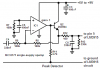
what do you need to add to this schematic to make it turns off only one led in the moment? and when you switch back, it shows as many leds as it should?
i have seen that somewhere...
https://www.electro-tech-online.com/attachments/vu-meter-with-gain-png.32468/
i have seen that somewhere...
https://www.electro-tech-online.com/attachments/vu-meter-with-gain-png.32468/
") i have just solved the problem by adding the switch between pin 9 and +12V. Now i have bar and dot mode.
i have just solved the problem by adding the switch between pin 9 and +12V. Now i have bar and dot mode.