Hi GT3,
concerning the pin count and number of parts (hence overall size of the circuit) I guess the best solution is still a transistor.
Using an integrated circuit you still require the timing components (R and C) + a current limiting resistor for the LED.
You should try to get a 2N6660 (TO39 package) or a BS170 (TO92 package). Both are about the same size (2N6660 has a metal can, and BS170 has plastic)
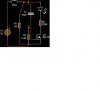
I reworked the design for an ON-time of 25 seconds and omitted the gate resistor (former R1). The cap has been changed to 10µF and the charge resistor to 3.3MΩ.
The LED stays on brightly for 25 seconds and fades out for further 5 seconds.
A green LED works fine, but you must observe to use a low current LED (If=2mA instead of a normal LED with an If of 20mA) as specified in the circuit.
The final current flow of 3µA is not affected by changing the values of the timing components.
Regards
Boncuk