Continue to Site

Welcome to our site!

Electro Tech is an online community (with over 170,000 members) who enjoy talking about and building electronic circuits, projects and gadgets. To participate you need to register. Registration is free. Click here to register now.

  • Welcome to our site! Electro Tech is an online community (with over 170,000 members) who enjoy talking about and building electronic circuits, projects and gadgets. To participate you need to register. Registration is free. Click here to register now.

What are the functions of Input Network in power amplifier?

Status
Not open for further replies.

hanhan

Member
Hi,
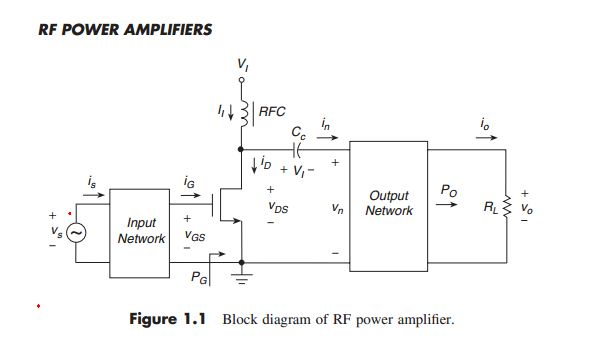
I am reading about RF power amplifier. Here is the block diagram of a RF power amplifier.
Can anyone tell me the functions of "Input Network" here?
And also I have read that RF choke used to provide approximate current constant. Is this right?
block-diagram-of-power-amplifier-jpg.75199
 

Attachments

  • Block diagram of power amplifier.JPG
    Block diagram of power amplifier.JPG
    26 KB · Views: 429
Last edited:
Input network can be: Output network might be:
1)Band pass filter, low pass filter, high pass filter.
2)Impedance matching circuit. example:75ohms in 200 ohms out.

approximate current constant= yes
 
Thanks ronsimpson,
Input network can be: Output network might be:
1)Band pass filter, low pass filter, high pass filter.
2)Impedance matching circuit. example:75ohms in 200 ohms out.
That makes sense!
approximate current constant= yes
Is my understanding correct?
RF choke is used to block RF signal and pass DC or low frequency signal. Therefore, the current flowing through transistor is only DC component or low frequencies and it is a constant.
 
Last edited:
A choke wants to took the current the same. (constant current) [not voltage]
A capacitor wants to keep voltage the same [not current]

The choke is big enough that current can not change much during one cycle of the RF.
It is true the the RF stays off the power supply in part because the choke blocks RF current from getting to the supply and there should be a capacitor from supply to ground that keeps the supply voltage constant.

The real purpose of the choke: If a resistor was used it will get hot. power loss The output voltage will be some where between ground and supply (max).
A choke wants to have 0 volts average across it. When the transistor is on, it makes half of the waveform from supply to ground. When the transistor is off it swings above supply by the same amount. So the output is from ground to 2x-supply. (max)
 
Status
Not open for further replies.

Latest threads

New Articles From Microcontroller Tips

Back
Top