Continue to Site

Welcome to our site!

Electro Tech is an online community (with over 170,000 members) who enjoy talking about and building electronic circuits, projects and gadgets. To participate you need to register. Registration is free. Click here to register now.

  • Welcome to our site! Electro Tech is an online community (with over 170,000 members) who enjoy talking about and building electronic circuits, projects and gadgets. To participate you need to register. Registration is free. Click here to register now.

Welding inverter outputing 90 vdc but no welding current.

Status
Not open for further replies.

BGAmodzX

Member
Hi everyone.

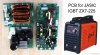
I have to repair a welding inverter.
The inverter has an output of 90 volts dc ,
but there is no welding current jus a tiny spark.

I should mention that i replaced 4. 40 amps IGBTs with 2 . 60 amps IGBTs. but the machine starts .

i checked the main blocks the auxiliary power supply is good . the potentiometer is good . the TL084N op amps which i guess control the overcurrent are replaced . the chopper area is clean.

Now i think the problem is eather the main oscillator or the output transformer that stops working under load .

I would like your opinion on this .

Thanks in advance for reading.
 

Attachments

  • igbt-zx7-200-pcb-for-jasic-zx7-200-225-igbt-inverter-welder.jpg
    igbt-zx7-200-pcb-for-jasic-zx7-200-225-igbt-inverter-welder.jpg
    83.4 KB · Views: 909
Don't quite understand why you would only replace 2 IGBTs when the board is expecting 4? And still expect it to work. My thoughts are if the board is made for 4 IGBTs it won't run with only 2.
 
Don't quite understand why you would only replace 2 IGBTs when the board is expecting 4? And still expect it to work. My thoughts are if the board is made for 4 IGBTs it won't run with only 2.
thanks .

The igbts are grouped in two paralell 40 amps pieces. witch makes them 4.
I have just replaced the two paralell 40 amps wih a single 60 amps igbt.

but the welding unit starts though . and it gives an output of 90 volts dc.
It just doesnt give current at the secondary . it doesnt weld .

What is weird is that the welder has a maximum current of 250 amps , and the primary igbts give only 160 amps in their original configuration.

Do you think the primary igbts should have complete current capability ? at least the original 160 amps ?
 
Last edited:
thanks .

The igbts are grouped in two paralell 40 amps pieces. witch makes them 4.
I have just replaced the two paralell 40 amps wih a single 60 amps igbt.

but the welding unit starts though . and it gives an output of 90 volts dc.
It just doesnt give current at the secondary . it doesnt weld .

What is weird is that the welder has a maximum current of 250 amps , and the primary igbts give only 160 amps in their original configuration.

Do you think the primary igbts should have complete current capability ? at least the original 160 amps ?

I don't know much about welders (and don't weld), BUT - I presume the 90V is a high voltage from a separate supply, and intended to initiate an arc, which then triggers the low voltage high current supply to do the weld?.
 
As it is an inverter welder the IGBTS are probably on the primary side (Mains side) of the high frequency transformer. the voltage on the secondary will probably be about 50 volts or less when welding so 250 amps at 50 volts would be 50 amps at 250 volts (The input voltage.) That is based on 100% efficiency but in practice it would be less than 100%. So if it was 80% efficient the primary current would be 62.5 amps. As there are two pairs of IGBTS it could be push pull design inverter. I suggest that you try to find the schematic on the web. (Or trace out the schematic.) so you can understand how it is designed to work.

Les.
 
I don't know much about welders (and don't weld), BUT - I presume the 90V is a high voltage from a separate supply, and intended to initiate an arc, which then triggers the low voltage high current supply to do the weld?.
hello .

As far as i understand from les jones post , this device is supposed to have high voltage low current at the input , and low voltage high current at the output for initiating the welding process .

I will first put back the 4 chopper igbts and see if the problem is from there .
Second i will change the oscillator
" UC3846 ". maybe there is somthing wrong with the duty cycle , i mean maybe the oscillator's signal amplitude is good but the duty cycle is bad.

Other than this i will check the transformer the main welding transformer . And will do a round up of the main pcb sections maybe some bad caps or something like this.

I unfortunatly dont have a schematic of this device .
If you need pictures i cant upload them for you.
 
I will first put back the 4 chopper igbts and see if the problem is from there .
Second i will change the oscillator
" UC3846 ".

So your just randomly changing things? You give two different names for the machine ZX7-225 and ZX7-200, can't find a 225 but here is a link to the 200 schematic - https://elektrotanya.com/EasyArc_zx7-200_igbt_inverter_welder.pdf/download.html Different brand name but is commonly done with Chinese products, the model is the important thing.
 
So your just randomly changing things? You give two different names for the machine ZX7-225 and ZX7-200, can't find a 225 but here is a link to the 200 schematic - https://elektrotanya.com/EasyArc_zx7-200_igbt_inverter_welder.pdf/download.html Different brand name but is commonly done with Chinese products, the model is the important thing.

Well assuming that circuit (poor as it is) is anything like what he's got, it's not surprising it doesn't work with only two FET's fitted, as the four are in a bridged configuration.
 
I have just replaced the two paralell 40 amps wih a single 60 amps igbt.
Why? That would reduce the output capability by 25%, assuming the inverter still worked..
 
hi again guys.
You were right about the 4 igbts configuration , i shoundt change what the topology imposes

i have put back the 4 igbts and the device is burning sticks as it should.
**broken link removed**
 
Status
Not open for further replies.

Latest threads

New Articles From Microcontroller Tips

Back
Top