Continue to Site

Welcome to our site!

Electro Tech is an online community (with over 170,000 members) who enjoy talking about and building electronic circuits, projects and gadgets. To participate you need to register. Registration is free. Click here to register now.

  • Welcome to our site! Electro Tech is an online community (with over 170,000 members) who enjoy talking about and building electronic circuits, projects and gadgets. To participate you need to register. Registration is free. Click here to register now.

weird transmitter

Status
Not open for further replies.

zachtheterrible

Active Member
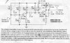
I built this here transmitter. I made a couple modifications though.

1. I put a .1 uf cap across the leads of the battery.

2. I made it so that I can put different types of capacitors in parralel wit the tuning cap, therefore adjusting the frequency.

3. I made a smaller value inductor.

I'm having a very funny problem though. I can tell when I have the transmitter on the same frequency as my radio because there is a silence, but no voice. When I do get my voice to come over, it is crystal clear, but when I don't say anything for a couple of seconds, it seems as if the transmitter is not even on because when I try to talk again, there is nothing . . . no silence or voice. Could the .1 uf cap that I put across the battery be the wrong value? Cuz it's not in the circuit, someone told me to do it.


THANX :D
 

Attachments

  • fmtrans_170.jpg
    fmtrans_170.jpg
    265.4 KB · Views: 360
When the RX and TX properly tuned at same frequency,no FM noise on RX. I mean this is a freq.stability problem in transmitter. When the noise coming back, try tuning the RX again, and You can find the signal at lower or higher frequency.
This is a common problem with small transmitters. The tank capacitor must be TK0 type and very stable, also the supply.
Without quartz never be long time stability...
 
Also try to shield it because your hand moving to and from the circuit
will affect it too.
 
Do u think that it could be C5? Cuz doesn't that make it so that the the signal doesn't degenerate? Or something along those lines. What is RX and TX? I know I know this, but I forgot. Thx. Also, would putting the .1 uf cap across the leads of the battery make it not work? Cuz as I said, it's not in the circuit. I saw it on a different circuit similar to this 1 that uses 3 volts. I'm supposed to put a .001 uf cap across the battery, but I heard that it doesn't realy matter, .1uf will do.
 
it's not C5. C5 is feedback required for circuit to oscillate and it's not critical. however even slight changes in capacitance in the osciloatory circuit (C4+L1) would cause frequency drift.
 
I REAAAAALY need my question about substituting the .1 uf cap for the .001 uf cap. PLEASE!!!!!!! :D :) :D :)
 
It will make no real difference, it's simply a decoupler across the supply, and 'something' should be fitted on almost all circuits - basically to keep the positive and negative supply rails at the same potential (as far as AC signals are concerned).

The value you used should be fine!.
 
What are some things that could cause frequency drift? Panic mode mentioned that small changes in the oscilatory circuit would cause this. The thing is, there are no changes in this part of the circuit that I know about. Not heat, not my putting my hand near the circuit or anything like that. Could having the inductor too close to C4 be doing this? Cuz they are practicaly touching, but if they did touch, it would be plastic to metal. Could it just be a bad C4?
 
Status
Not open for further replies.

Latest threads

New Articles From Microcontroller Tips

Back
Top