Continue to Site

Welcome to our site!

Electro Tech is an online community (with over 170,000 members) who enjoy talking about and building electronic circuits, projects and gadgets. To participate you need to register. Registration is free. Click here to register now.

  • Welcome to our site! Electro Tech is an online community (with over 170,000 members) who enjoy talking about and building electronic circuits, projects and gadgets. To participate you need to register. Registration is free. Click here to register now.

Weird problem with 16f628

Status
Not open for further replies.

c36041254

Member
Hi there!
I have written a programme for a line follower robot ( though still not implemented), first I want to try it with LEDs, Here is the code :

Code:
list p=16f628
		#include<p16f628.inc>
		__CONFIG  _MCLRE_ON & _CP_OFF & _WDT_OFF & _INTRC_OSC_NOCLKOUT
		ERRORLEVEL   -302
		cblock	0x20
			temp 
			temp_s      
  		endc
;******************************************************************
	org 0x00
	goto main
;***********************************INTERRUPT LOOP*****************
	org 0X04
inter:
		movwf temp
		swapf STATUS,w
		clrf  STATUS
		movwf	temp_s
		btfsc	PORTB,0x00
		goto	loop1
loop2:
		movlw b'00000101'
		movwf	PORTA
		btfsc	PORTB,0x05
		goto	loop2
		goto	loop_x
		
loop1:		
		movlw b'10001000'
		movwf PORTA
		btfsc PORTB,0x00
		goto  loop1
loop_x
		bcf   INTCON,0x01
		bcf	  INTCON,0x00
		swapf temp_s,w
		movwf STATUS
		swapf temp,w
		retfie

main:
	bsf	INTCON,0x07			;Globel interrupt enable(we are using interr.)
	bsf INTCON,0x04	
	bsf	INTCON,0x03			;RB4-RB7 interrupt on change is enabled/ in other words these pins will also work as
							;interrupts and interrupt will occur every time any of these pin changes state
							; i.e.:HIGH to LOW or LOW to HIGH, we can not set it to be on eather one state change  		
	bcf INTCON, 0x01		
	bcf	INTCON,	0x00			;Clear RB4-RB7 interrupt flag so, that another interr. can occur.

;**********************************SET UP THE PORTS *****************
	bsf	STATUS,RP0			;switch to BANK 1
	movlw b'00100001'	
	movwf TRISB				;set RB6 & RB5 as input
	movlw b'00000000'
	movwf TRISA				;setPORT A all output
	bcf OPTION_REG,0x07		; enable weak pull ups on port b/ pull ups mean internal resistors
	bcf STATUS,RP0			;back to BANK  0
	movlw 0x07				;turn comparators off, so HIGH will be simple
							; HIGH rather than +5V (compared to supply) so with the LOW
	movwf CMCON				

Loop:

	movlw b'00001001'		
	movwf PORTA				;set pin 0 of port a HIGH
	goto Loop
	END


Now let me explain you what this code supposed to do (which it does very well but only when the PIC is powered by PIC Kit 2):

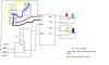
First when the power turned on RA0 and RA3 goes HIGH lighting YELLOW and GREEN LEDs, and when I press switch 1, RB0 goes high and an interrupt occur and YELLOW LED switched off and BLUE LED lights up and same sequance is applicable to RED and GREEN LEDs when I press switch 2 which causes interrupt at RB5

Again let me tell you that the PIC runs this programme very well BUT ONLY WHEN IT IS POWERED BY PIC KIT 2 AND NOT WHEN CONNECTED EXTERNALLY AS SOWN IN CKT.

PLEASE, don't check that this code is o.k. for a line follower or not or don't tell me that there is a better code for that I know ther are many, I'm a layman (see how I learned PIC programming on thread titled" setup an interrupt in 16f690") , I JUST WANT TO ASK THAT WHY IT IS NOT WORKING WHILE POWERED EXTERNALLY ?
By not working I mean :

When I turn on the power YELLOW and GREEN LEDs lights up as it should be but, on either interrupt both LEDs goes off lightning NO OTHER LED, I tried tieing MCLRE high and even LOW but nothing work.
PLEASE HELP ME !!:(

Edit: Kindly see the circuit that is exactly how I connect it, nothing more nothing less
 

Attachments

  • PIC robo.jpg
    PIC robo.jpg
    30.1 KB · Views: 486
Last edited:
You don't have any capacitors on your power supply.
Also, it's not a good idea to drive LEDs straight from a pic without resistors.
 
I JUST WANT TO ASK THAT WHY IT IS NOT WORKING WHILE POWERED EXTERNALLY ?
By not working I mean :

When I turn on the power YELLOW and GREEN LEDs lights up as it should be but, on either interrupt both LEDs goes off lightning NO OTHER LED, I tried tieing MCLRE high and even LOW but nothing work.
PLEASE HELP ME !!:(
To run properly without a programmer attached, MCLR must be pulled high with a pullup resistor. Use any value from 10K to 33K (I always use 33K). Pulling it low just puts the chip in reset - nothing happens till it goes high again.

You should have a 0.1uF ceramic capacitor close to the chip from VDD to VSS, and a 10uF electrolytic (or bigger) is a good idea somewhere near the chip from VDD to VSS (observe polarity).

As House0Fwax says, put (typically) 330 ohm current limiting resistors in series with each LED. 180 ohm to 470 ohm is the typical range for current limiting resistors on LEDs. Depends on your LEDs and how bright you want them.
 
Last edited:
I understand that I need to couple the AC and so I tried this (see the ckt), but that is not working infact LEDs are now start blinking (red and yellow ). I don't get what do you mean by "...somewhare near the chip....", I mean whether it is near the chip or even at long distance , should not make any difference as far as the caps are across the Vdd and Vss.
 

Attachments

  • PIC robo.jpg
    PIC robo.jpg
    32.8 KB · Views: 341
Last edited:
You definitely need a resistor from MCLR to 5V for the pic to run, if this is missing the pic may run intermittently and produce flashing LEDs. This is normally taken care of by the Pickit2 but once you remove it, you have to supply the resistor.

Also, if your 9V supply is a wall wart then you may need an electrolytic on the 9V side. You should also have a 0.1uF capacitor on both sides of the regulator and a small electrolytic on the 5V side. The 104pF capacitor is probably a 0.1uF anyway - 0.1uF capacitors are marked 104, that is 10 + 4*zeros after = 100,000pF = 0.1uF. It is important that the 0.1uF cap is near to the pic pins, this is to suppress fast switching currents. I'm sure you have checked it anyway but have you checked the obvious things like the voltage on the actual pic chip, many problems here have been solved with a new battery.

Mike.
 
Mike I have attached a 10k resistor as pull up for MCLRE but, haven't apply any cap. on 9v side so I'll try that. Thanks for help !
 
I don't get what do you mean by "...somewhare near the chip....", I mean whether it is near the chip or even at long distance , should not make any difference as far as the caps are across the Vdd and Vss.
Physically and electrically (same thing) as close to the chip as possible. See the tiny light brown/orangish 0.1uF caps across VDD/VSS on both sides of this chip. This breadboard is controlling a motor controller and there are motors about 1/2" away too, and the whole thing runs off the same battery pack (breadboard has its own regulator) so there are a few extra electrolytics to smooth out any buzz and/or dips in the power.
bleh_sm.jpg
At the bottom left you can see the 33K MCLR pullup resistor right beside the power LED's current limiting resistor.
 
O.K. Ihave done the caps and attached the resistors to LEDs but, still only one switch (RB0 interr.) is working and that too when I have my fingure on the polar acp connected across Vss and Vdd. I have attached a pull down resistor of 10k on RB0, doing the same at RB5 stops the PIC and all LEDs goes off:(:(
 
I spent a whole day on that and found this:

When I ground the RB0 the RB5 interr. works fine and when ground the RB5 the RB0 works fine, with pull down resistors connected to both it should not be necessary to ground the interr. manualy but that's not happening. Is thare any way (except transistors) by which RB0 automatically gets grounded while giving high to RB5 and vice versa. When these interr. will be connected with phototransistors I think this will be resolved. Let me know if there is any other solution to this.:confused::confused:
 
I spent a whole day on that and found this:
I spent an hour or so and found this: :D 
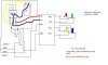
Your code needs those pulldown resistors you have in your schematic. Turning on the weak pullups in the chip just screws things up.

I made some minor corrections to the code, but nothing that changes the fundamentals of how you were doing things:
Code:
	list p=16f628
	#include <p16f628.inc>
	__CONFIG  _MCLRE_ON & _LVP_OFF & _WDT_OFF & _INTRC_OSC_NOCLKOUT
	ERRORLEVEL   -302

	cblock	0x20
	w_temp,status_temp
  	endc

	org	0x00
	goto	main

	org	0X04
inter	movwf	w_temp		;preserve regs
	swapf	STATUS,w
	bcf	STATUS,RP0
	movwf	status_temp
	btfsc	PORTB,0		;RB0 switch pressed?
	goto	loop1		;yes, go handle it
loop2	movlw	b'00000101'	;RB5 switch pressed, red & yellow LED on
	movwf	PORTA
	btfsc	PORTB,5		;keep them lit till switch released
	goto	loop2
	goto	loop_x		;RB5 switch released, go return
loop1	movlw	b'10001000'	;green & blue LED on
	movwf	PORTA
	btfsc	PORTB,0		;keep them lit till switch released
	goto	loop1
loop_x	bcf	INTCON,INTF	;clear interrupt flags
	bcf	INTCON,RBIF
	swapf	status_temp,w	;restore regs & return
	movwf	STATUS
	swapf	w_temp,f
	swapf	w_temp,w
	retfie

main
	banksel	TRISB		;bank 1
	clrf	TRISA		;PortA all outs
	movlw	b'00100001'	;RB0 & RB5 inputs
	movwf	TRISB
	banksel	PORTA		;bank 0
	movlw	0x07		;comparators off
	movwf	CMCON				
	movlw	b'10011000'	;set interrupts
	movwf	INTCON
Loop	movlw	b'00001001'		
	movwf	PORTA		;RA0 & RA3 high
	goto	Loop

	end

Here's a YouTube movie of it in action:

And here are some pics of the circuit for you to compare with yours. Those are 330:eek:hm: current limiting resistors on the LEDs. The MCLR pullup is 22K:eek:hm:. The power LED has a 180:eek:hm: resistor. The switch pulldowns are 10K:eek:hm::
c36041254_001sm.jpgc36041254_002sm.jpgc36041254_003sm.jpgc36041254_004sm.jpg

My power supply is a wall wart plugged into **broken link removed**, so the capacitors on the breadboard are really redundant and unnecessary for me. I put them there for your benefit. There are a 100uF and 10uF electrolytic and a 0.1uF ceramic on there.
 
Last edited:
Thank you ! futz turning off the WPUs work !:), why they were causing the problem ?. Now, this may suitable for general topic but, still I'm puting it here.....

I have just finished my diploma in electronics and telecommunication (Bachlor's running) so, I was wondering that at this stage, is it normal to have this much knowledge (whatever you can make out of this discussion ), I am very nervous about all this, it was just a very simple programme and still took so long for me ! and there was Mike who explained me what was 104pF (104pF = 0.1uF):eek:, after having a diploma I'm making an impression that I even don't know how to read 104pF:eek::eek:, I'm sure Mike was just helping me but, all these makes me realy nervous, Does this usually happens or I'm a dumb elcectronics hobbiest and need to study hard ?, though in my class I am the smartest one (trust me my teachers say so ;)) (don't be polite in responding)
 
Thank you ! futz turning off the WPUs work !:), why they were causing the problem ?
You can't have pullup and pulldown on the same switch. I'm not positive that was the whole problem anyway. A switch that is pulled down to ground with a resistor is expected to go high when pressed. If it is pulled up to VDD it is expected to go low when pressed. Your code expected the switches to have pulldowns and go high when pressed. Adding pullups into that is just confusing. You probably ended up with a halfway voltage that might or might not trigger the interrupt, sometimes. :p It was probably effectively floating. A floating pin can do random things.

There were a couple things in your code that may have been causing trouble too. I forgot to make notes while I was going thru it, so I don't know the details. You can compare and see for yourself.

I have just finished my diploma in electronics and telecommunication (Bachlor's running) so, I was wondering that at this stage, is it normal to have this much knowledge (whatever you can make out of this discussion ), I am very nervous about all this, it was just a very simple programme and still took so long for me ! and there was Mike who explained me what was 104pF (104pF = 0.1uF):eek:, after having a diploma I'm making an impression that I even don't know how to read 104pF:eek::eek:, I'm sure Mike was just helping me but, all these makes me really nervous, Does this usually happens or I'm a dumb electronics hobbiest and need to study hard ?, though in my class I am the smartest one (trust me my teachers say so ;)) (don't be polite in responding)
What? You're supposed to know more than me! I'm just a hobbiest tinkerer. Never been to school for any of this stuff. Sometimes I wonder about what they're teaching in those schools... :p

Anyway, the only way to learn how to program well is to write programs! LOTS of them. Practice, practice, practice until it becomes "easy".
 
Last edited:
This is why it is better to use the internal pullups (where available) with the switches pulling the pin low. Your pull downs must have been 20K or higher as the internal ones are (nominally) 20K.

Don't worry too much about your lack of abilities. As Futz said, you just need practice.

Mike.
 
Status
Not open for further replies.

Latest threads

Back
Top