Continue to Site

Welcome to our site!

Electro Tech is an online community (with over 170,000 members) who enjoy talking about and building electronic circuits, projects and gadgets. To participate you need to register. Registration is free. Click here to register now.

  • Welcome to our site! Electro Tech is an online community (with over 170,000 members) who enjoy talking about and building electronic circuits, projects and gadgets. To participate you need to register. Registration is free. Click here to register now.

Water Electrolysis Power Supply - 250KHz, 1:3 Duty Cycle, +26V 50A

Status
Not open for further replies.

pnielsen

Member
I would like to build a power supply for experimenting with water electrolysis. The information I have calls for a square wave pulse, timed 0.001ms "on" and 0.003ms "off" (250KHz). It is supposed to supply +26V at 50 amps into the cell.

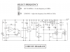
I am considering the power stage of the attached circuit. But rather than build a signal generator from scratch, I intend to connect a function generator at the junction of IC1/2 pin 1 and R11.

Am I on the right track or can someone suggest a better solution?

If the 250KHz is problematic, it may be possible to reduce it to as far as 25KHz.
 

Attachments

  • pwm_power_supply.png
    pwm_power_supply.png
    70.8 KB · Views: 199
Last edited:
He's asking for 0.001 mS on and 0.003 mS off, which is a period of 4 uS. So that will be 250 KHz.
 
Originally he didn't.

Seems you're making a 1kW 250kHz transmitter.

Mike.

Sorry Mike.

I now see the timing of the edits.

It always frustrates me when posters do that. It makes it hard to follow the continuity of a thread.

It's far better to make another post with the corrected information.
 
Originally he didn't.

Seems you're making a 1kW 250kHz transmitter.

Mike.

Yes, Mike is correct he was not seeing things. The original post was edited after that detail was brought out in the thread.

Inq
 
Sorry. Should have picked that up. It is 250kHz. I have edited my original post accordingly. Thanks
pwm_power_supply-png.114287

I am a little confused as usual. The text says hz or khz who knows and the picture from #1 clearly says hz.
The poor way the MOSFET's gate driver is built it must be hz. (slow not fast)
---edited----
Please show a link to where you got this circuit from.
 
Last edited:
My apologies for error in my OP. The diagram I attached specified it is capable of up to 3KHz, and I mentioned 25KHz would be acceptable if 250KHz is not. It is a PWM speed controller. I was considering to use or adapt the power stage after IC1/2.

If there is a problem with the gate driver, where can I find a better cuircuit? Note that this is intended to power an eletrolytic cell, not transmit RF.

Can we continue on this basis or should I repost this thread?
 
If you have a function generator that you can set for the frequency and duty cycle that you want, then just use it to drive a mosfet gate driver.
Here is one that is still available in a DIP package. **broken link removed**

The output of the mosfet driver drives the mosfets, but I recommend a resistor (10 to 100 ohms) in series with the gate of each mosfet.

Stay with this thread. No reason to start a new one.
 
The IR2110 is a highside and a lowside drver, instead of only a lowside driver like the one I proposed, and like your original circuit.

See that extra Q1 mosfet? It pulls the output up to the positive supply rail. Do you need that?
 
Thank you for your suggestion. Yes, I probably don't need the high side feature, unless it has better load driving properties I have yet to learn about. All I want is current flow from the cell's positive electrode to the negative.

Do you see any need to improve upon the circuit below? The original circuit I posted used two N-channel MOSFETs in parallel and seemed to have extra protection. I need to supply about 50A at 26V to the cell, which is not a typical load, and ensure the driver will not be adversely affected.

low_side_driver.png


https://microcontrollerslab.com/use-mosfet-driver-1r2110/
 
Status
Not open for further replies.

Latest threads

New Articles From Microcontroller Tips

Back
Top