Electro Tech is an online community (with over 170,000 members) who enjoy talking about and building electronic circuits, projects and gadgets. To participate you need to register. Registration is free. Click here to register now.
Welcome to our site! Electro Tech is an online community (with over 170,000 members) who enjoy talking about and building electronic circuits, projects and gadgets. To participate you need to register. Registration is free. Click here to register now.
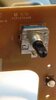
I want to replace this volume controller in my Philips mini hi fi system. I cannot find any part number or type of this?
Anyone knows? In the service manual it does not mentioned the part number, Only the schematic is there
It's a simple quadrature encoder, a mechanical rather than optical type.
Count the steps for one full revolution; the "line count" or pulse count will either be the same as that, or 1/4 that. See if there are any similar numbers on the existing encoder?
It's a simple quadrature encoder, a mechanical rather than optical type.
Count the steps for one full revolution; the "line count" or pulse count will either be the same as that, or 1/4 that. See if there are any similar numbers on the existing encoder?
A small squirt of WD40 inside them often helps a great deal - and good luck finding an exact replacement, generally the ones you see in domestic electronics are different to ones you can find for sale.
BIt too much oil in my opinion, and not enough solvent - WD40 (or Servisol Super 40) always seemed the best option for contact, switch and volume control cleaning, and we used it exclusively for decades (after years of using various less effective methods).
Taking the discussion of the rotary encode in a slightly different direction for a moment...
Taking the schematic in the first post and kicking it about a bit, I get this:
To me this is rather strange for an encoder (maybe my experience is lacking?), but there is only one signal to the processor (?).
Where I would have expected two signals, square waves in quadrature,
this circuit will be giving one signal which will an analogue signal with four discrete levels.
Nice point.There is nowhere in the datasheet mentioned as a Rotary Encoder.The silk screen ledgend printed "Rot1".Somewhere in the datasheet mentioned "Rotator".
Nice point.There is nowhere in the datasheet mentioned as a Rotary Encoder.The silk screen ledgend printed "Rot1".Somewhere in the datasheet mentioned "Rotator".
And 'clicks' slightly as it does so, it's a rotary encoder - it's EXTREMELY common on electrical brown goods.
The circuit section clearly shows it as a rotary encoder, even labelling the pins ground, A and B - although (as Jim says) it's a bit peculiar having different value pull-up resistors and a single wire feed. I would presume that makes it more difficult to read, but does save an I/O pin on the processor - presumably they had run out
Looks like a standard rotary encoder - it makes it more difficult because it's mounted on a larger board - quite often the encoder is mounted on it's own small board (complete with it's resistors), and bolted to the front panel via it's own nut. It then connects to the main board via a small lead and plug.
That type means you can fit pretty well anything, and just solder the original lead and plug to it - as yours is mounted directly on a larger PCB, you really need one that's an exact fit.
I presume one of the reasons for using them is to get over noisy volume control problems, but the rotary encoders are no more reliable than volume controls.
There are two switches A an B
Each switch can be open (0) or closed (1)
Drawing a truth table
A B
0 0
1 0
0 1
1 1
That is four states.
Looking at the schematic fragment
In the 0 0 state, the voltage at ROT_A/B will be 3.3v
In the 1 0 state, the voltage at ROT_A/B will be 2.2v
In the 0 1 state, the voltage at ROT_A/B will be 0.148v
In the 1 1 state, the voltage at ROT_A/B will be 0.145v
So four different voltage values.
Admittedly two of those voltages are close together, and depending on the resolution of the ADC which is reading them they my give the same digitised value.
This site uses cookies to help personalise content, tailor your experience and to keep you logged in if you register.
By continuing to use this site, you are consenting to our use of cookies.