Electro Tech is an online community (with over 170,000 members) who enjoy talking about and building electronic circuits, projects and gadgets. To participate you need to register. Registration is free. Click here to register now.
Welcome to our site! Electro Tech is an online community (with over 170,000 members) who enjoy talking about and building electronic circuits, projects and gadgets. To participate you need to register. Registration is free. Click here to register now.
You do not show a schematic with a 2N2222 so we do not know what is A, B, C, D and E. We do not see if it is connected correctly.
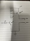
In post #2 you were shown a "high side switch" circuit.
You do not show a schematic with a 2N2222 so we do not know what is A, B, C, D and E. We do not see if it is connected correctly.
In post #2 you were shown a "high side switch" circuit.
Before the motor was connected to ground but now it is connected to +12V and its other end is connected to the collector of a 2N2222 transistor.
The motor needs a diode parallel to it with the cathode at the +12V end of the motor.
The motor speed control will work fine with PWM.
Before the motor was connected to ground but now it is connected to +12V and its other end is connected to the collector of a 2N2222 transistor.
The motor needs a diode parallel to it with the cathode at the +12V end of the motor.
The motor speed control will work fine with PWM.
Thank you. Mmm, adding the fly back diode maybe a problem.
What you said is true and this is how I’m controlling the power for the motor, but I am pushing the power into the board attached. The board attached controls my direction and so on, do I just put the diode across the positive and negative terminal of the motor power, this is adding the extra complex. I have not testing yet with this board attached yet but that’s my next step.
Is having a single 2N2222a ok on the negative side of the motor to control motor supply?
You cannot use a diode if the motor needs to run forwards and backwards. You need a voltage suppressor like two 15V zener diodes in series.
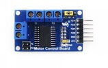
The photo of the Motor Control Board is useless without connection instructions and the missing part number of its important IC.
The 2N2222 probably will not work with the Motor Control Board.
You cannot use a diode if the motor needs to run forwards and backwards. You need a voltage suppressor like two 15V zener diodes in series.
The photo of the Motor Control Board is useless without connection instructions and the missing part number of its important IC.
The 2N2222 probably will not work with the Motor Control Board.
Your right. The pwm of the 2n2222a on the low side of the motor power does not work. It seems there is an internal ground link within the module. So therefore the ground I’m switching is useless.
I have tried to swap the 2n2222a to high side of the motor and that did not work either. It’s back to my original idea of relays switching the supply voltage or has anyone else have any idea how I could use PWM to vary the input voltage.
A two-transistor drive circuit, as I originally described. Just one, fed from 12V, with PWM control.
The motor definitely needs a flywheel diode. That should always be connected in whichever direction is does not conduct when power is applied to the motor.
This site uses cookies to help personalise content, tailor your experience and to keep you logged in if you register.
By continuing to use this site, you are consenting to our use of cookies.