Continue to Site

Welcome to our site!

Electro Tech is an online community (with over 170,000 members) who enjoy talking about and building electronic circuits, projects and gadgets. To participate you need to register. Registration is free. Click here to register now.

  • Welcome to our site! Electro Tech is an online community (with over 170,000 members) who enjoy talking about and building electronic circuits, projects and gadgets. To participate you need to register. Registration is free. Click here to register now.

Voltage rises across piezo buzzer when connected!

Status
Not open for further replies.

nzoomed

Member
I dont understand what's going on here, but it seems to be doing it with several different types, except for a small PCB mount one I've got.
Specs say supply voltage is 3-12V.
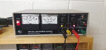
I have my lab power supply set to 5V.
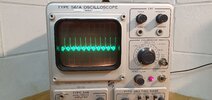
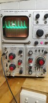
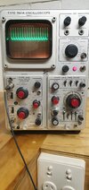
But the voltage rises on the meter when I connect the buzzer!
My multimeter reads about 7V when connected but drops back to 5V once I disconnect the buzzer.
Any ideas?
I also notice the dropout light comes on when connected.
Doesn't make any sense since these things draw little to no current.

I am using this with an arduino so don't want the 5V rail to do silly things and blow up the microcontroller.
I haven't tested with the arduino power supply yet to see if it does anything silly.
Perhaps its just this lab power supply that's behaving weird?
16638038602966424447881905698196.jpg
 
Since it's an oscillator, it will draw current in pulses, which could be pumping up the voltage.

Do you have a scope to look at the actual voltage waveform at the buzzer?
 
Since it's an oscillator, it will draw current in pulses, which could be pumping up the voltage.

Do you have a scope to look at the actual voltage waveform at the buzzer?
I was wondering if it had something to do with that, im wondering if the power supply I've got doesn't like it. Would a capacitor across the unit address this?
I do have a scope I could try and view the waveform with.
I'm assuming it might just be the nature of this power supply. I've just tested on another lab supply and got no issues and reads a constant voltage, im using a buck converter on this arduino with an lm2596, it appears to work fine but gives a slight voltage drop, but that's better than overvoltage.
 
As for why the one on a PCB does show this behavior, it may be due to it's distance from the source power supply capacitance.

Try a few experiments.

Place a small capacitor across the buzzer. Is the strange voltage still there?

Significantly change the length of the wire between the bench supply and the buzzer. Does the voltage change?
It wasn't on a PCB at the time, ive tested all these directly to the power supply itself. The pcb one is smaller however and less loud.
I will see what a capacitor does anyway.
 
This is an easy EMI stability test for any power supply by creating a short current spike that affects the FB voltage compensation filter to raise the voltage. Congrats. ;>}

The HPM24BX-1 piezo buzzer only draws an average of 2.5mA @ 5V but the impulse current may be >>10x higher for << 1/10x 100% of the duration of its 2800 Hz or 357 / 2 us resonance interval. That's equivalent to only a 2Kohm load so adding 100 Ohms in series would hardly attenuate it. Adding that series R might change the sound quality which could be fixed with a ceramic cap. if need be. But I doubt it.

Shunting the whole power supply output may require a much bigger capacitor with a very low ESR because of the low driver resistance.

Now you can measure the current on a scope and see why your supply responded so badly to a disturbance from poor compensation, layout or noise sensitivity.

Put the resistor on the negative side of the piezo buzzer. Try different values. Then report back the results for Vrise vs I peak and Rs. You may expect the crest factor or pk/avg to be the same as interval to pulse width (PW50). I guessed > 10x but what are the other guesses? 100x?

1663868610462.png
 
Last edited:
This is an easy EMI stability test for any power supply by creating a short current spike that affects the FB voltage compensation filter to raise the voltage. Congrats. ;>}

The HPM24BX-1 piezo buzzer only draws an average of 2.5mA @ 5V but the impulse current may be >>10x higher for << 1/10x 100% of the duration of its 2800 Hz or 357 / 2 us resonance interval. That's equivalent to only a 2Kohm load so adding 100 Ohms in series would hardly attenuate it. Adding that series R might change the sound quality which could be fixed with a ceramic cap. if need be. But I doubt it.

Shunting the whole power supply output may require a much bigger capacitor with a very low ESR because of the low driver resistance.

Now you can measure the current on a scope and see why your supply responded so badly to a disturbance from poor compensation, layout or noise sensitivity.

Put the resistor on the negative side of the piezo buzzer. Try different values. Then report back the results for Vrise vs I peak and Rs. You may expect the crest factor or pk/avg to be the same as interval to pulse width (PW50). I guessed > 10x but what are the other guesses? 100x?

View attachment 138719
Thanks, I will do a test on this.
I was told something else to try is to shunt the buzzer by putting a zener diode across it.
 
A zener might be a waste of time unless it can absorb the energy of the power of the supply over-reacting to the negative pulse.

The trick here is to limit the impulse currents without attenuating the sound using an RC filter. Ic=C*dV/dt The alternating impulse current accelerate the motion of the crystal and you end up with lots of harmonics, Slowing it down makes it more sinusoidal but quieter.
 
Last edited:
A zener might be a waste of time unless it can absorb the energy of the power of the supply over-reacting to the negative pulse.

The trick here is to limit the impulse currents without attenuating the sound using an RC filter. Ic=C*dV/dt The alternating impulse current accelerate the motion of the crystal and you end up with lots of harmonics, Slowing it down makes it more sinusoidal but quieter.
Ok, well my main concern isif it's going to cause any issues with my arduino microcontroller.
The voltage appears stable with the arduino power supply, so I guess that's a good thing?
But either way any measures to protect the rest of the electronics is a good thing.

I will do these tests after work tonight.
 
Well I tried as you said and connected the resistor in series to the negative.
It didn't make any difference, so I grabbed put my resistance wheel and went through everything. The voltage started to rise at around 500 ohms. Anything lower it got worse, but at 500 ohms it was noticeably quieter.
Tried placing a few ceramic caps across with no effect.
 
Here is the scope reading when the buzzer is connected. With my other power supply its barely noticeable
Where is zero and what are the volts per division?

What is the period of the spikes? Does the audio frequency match the spikes or the fuzz at the bottom?
 
Where is zero and what are the volts per division?

What is the period of the spikes? Does the audio frequency match the spikes or the fuzz at the bottom?
I would have set the zero on the trace one line below the centre from memory, unfortunately my scope has given out shortly after I took the photo, which is now another distraction!
It would have been on 2 volts per division at the time.
Not sure what you mean about the period of the spikes, I have no idea what frequency the one I am testing it with runs at. I have no idea how to check if the audio frequency is matching the waveform above.
You do so from the timebase setting, which control wasn't shown in the picture. The setting shows how much time is represented by one horizontal division.
 
You do so from the timebase setting, which control wasn't shown in the picture. The setting shows how much time is represented by one horizontal division.
I've got the scope working again, an electrolytic cap had blown on it.
I've set zero to the centre of the scope, division is 5v, time delay is 2ms.
I've got it to give a clean trace if I put an electrolytic cap across the buzzer, bit it changes its pitch and to some degree it's volume. I might need to experiment with values.
This is the only thing I find makes a difference.
The waveform does indeed change with the pitch of the buzzer if I cover it for example, the waveform changes on the scope.
 

Attachments

  • 20221001_130206.jpg
    20221001_130206.jpg
    970.3 KB · Views: 168
Last edited:
I've set zero to the centre of the scope, division is 5v, time delay is 2ms.

Allow me to be a bit critical of your terminology...

When you say "division is 5v",
it would be better to say " the vertical scale is 5v per division"

When you say "time delay is 2mS",
delay has nothing to do with it.
The timebase is set to 0.2mS per division, a factor of 10 difference.
But also the red Variable knob is not turned fully clockwise, as confirmed by the illuminated "Uncal" indicator.
Turn the red Variable knob fully clockwise and start again.

As for your original problem of spikes changing apparent applied voltage, I suggest that as the buzzer just needs a DC supply, you should put a capacitor across the buzzer terminals.
Try something between 1 and 10uF.
Then look again with the scope, if the spikes have gone away call it good and move on.

However, this does leave the thought that there is something a bit odd about your "lab power supply".
Does the PSU have a current limit control?
And if it does, is that control turned right down so that the PSU is going in to current limit as the buzzer draws current pulses from the supply?

JimB
Sorry, I forgot the decimal point, yes its .2ms, didn't realise that was per division.
Yes the power supply has current limit, and I've turned it up all the way. Makes no difference at all whether the current limit is maxed out or turned right down, other than the volume dropping off a bit at the very lowest current.
I dont think its ultra high quality, it was built from a dick Smith kit.

I thought the Variable red knob on the scope is what is used to lock the signal, it will keep scrolling across the screen at times and I can turn it to keep it still.
Although I managed to get it steady with it switched off as seen here.

Anyway I will try lowering capacitors as you say, my main concern is just engineering this right. Some buzzers are worse than others, bit I don't want to risk any voltage spikes on the power to the microcontroller.
 

Attachments

  • 16645935420656881774648437501774.jpg
    16645935420656881774648437501774.jpg
    2 MB · Views: 167
  • 20221001_155643.jpg
    20221001_155643.jpg
    999.6 KB · Views: 176
I thought the Variable red knob on the scope is what is used to lock the signal, it will keep scrolling across the screen at times and I can turn it to keep it still.
Although I managed to get it steady with it switched off as seen here.
That is not the correct way to use that control.

The "normal" way to use it, is to have it turned fully clockwise until the UNCAL lamp is extinguished.
Then the timebase is calibrated as per the numbers on the big switch, ie 0.5mS per division in your last picture.

The correct way to make the waveform display stand still, is by use of the timebase trigger controls.
In the last picture, the triggering switches are set to sensible positions, but the "trigger level" control is probably not well set.
See the picture below:

1664622478173.png


Try turning the trigger level control anti clockwise so that it is somewhere in the middle of its rotation.

Something which complicates the issue is that this scope has a dual timebase for delayed sweep operation. This can cause a lot of confusion for a beginner.


Otherwise, that is a nice old scope that you have there.

JimB
 
That is not the correct way to use that control.

The "normal" way to use it, is to have it turned fully clockwise until the UNCAL lamp is extinguished.
Then the timebase is calibrated as per the numbers on the big switch, ie 0.5mS per division in your last picture.

The correct way to make the waveform display stand still, is by use of the timebase trigger controls.
In the last picture, the triggering switches are set to sensible positions, but the "trigger level" control is probably not well set.
See the picture below:

View attachment 138802


Try turning the trigger level control anti clockwise so that it is somewhere in the middle of its rotation.

Something which complicates the issue is that this scope has a dual timebase for delayed sweep operation. This can cause a lot of confusion for a beginner.


Otherwise, that is a nice old scope that you have there.

JimB
Yeah I have to be honest I don't know alot about these scopes. Other scopes I've used are much simpler and have less controls.
It's quite a nice old piece of kit and still appears to work well but could do with a service and replace some of these old leaky caps..
I got it for $20 at a ham radio sale and figured it would be something worth taking since it's tektronix!

I will take a look at that trigger control. From memory it didn't do much when adjusting it.
The knob also pulls out for "external" trigger.
Not sure how that works yet.
 
Status
Not open for further replies.

Latest threads

New Articles From Microcontroller Tips

Back
Top