Electro Tech is an online community (with over 170,000 members) who enjoy talking about and building electronic circuits, projects and gadgets. To participate you need to register. Registration is free. Click here to register now.
Welcome to our site! Electro Tech is an online community (with over 170,000 members) who enjoy talking about and building electronic circuits, projects and gadgets. To participate you need to register. Registration is free. Click here to register now.
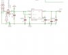
Not sure what the regulation voltage is for the IRU1205 because the variant isn't specified in the schematic.
The variation is as follows:
IRU1205CL= Adjustable
IRU1205-18CL= 1.8V
IRU1205-25CL= 2.5V
IRU1205-28CL= 2.8V
IRU1205-30CL= 3.0V
IRU1205-33CL= 3.3V
IRU1205-36CL= 3.6V
The drop out voltage is between 10mV and 400mV depending on the amount of current you are drawing.
Pin 1 is the input voltage (max of 10V)
Pin 2 is the ground pin
Pin 3 is the enable pin
Pin 4 is the adj/Cbp - either the voltage adjust pin for variable regulator version, or the bypass capacitor for all other versions
Pin 5 is the output
I'm going to agree with ronsimpson on the MOSFET, I'ts probably there to protect the battery although a regular diode could have done that job just as well. I thing the MOSFET is a redundancy and unless the designer intended to use it to shutdown the circuit, you can probably get away with not using it.
This site uses cookies to help personalise content, tailor your experience and to keep you logged in if you register.
By continuing to use this site, you are consenting to our use of cookies.