Continue to Site

Welcome to our site!

Electro Tech is an online community (with over 170,000 members) who enjoy talking about and building electronic circuits, projects and gadgets. To participate you need to register. Registration is free. Click here to register now.

  • Welcome to our site! Electro Tech is an online community (with over 170,000 members) who enjoy talking about and building electronic circuits, projects and gadgets. To participate you need to register. Registration is free. Click here to register now.

Voltage regulation problem

Status
Not open for further replies.

revans

New Member
My current problem hitches around the circuit I'm using to manage the power side of things in my boombox-in-progress:
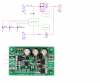
picoUPS-100 12V DC micro UPS system / battery backup system ... **broken link removed**

This guy explains it well:
A brief comment about the picoUPS-100: It can run off 6-18V DC which at first seems pretty flexible. However, it can only charge the battery when supplied with at least 15V. While this may seem reasonable enough, the board does no conversion of its input voltage -- if input voltage is higher than battery voltage, it simply routes the input voltage directly to the UPS output. What this really means is that the devices you run off the UPS need to function with 15V, and they need to be able to handle voltage suddenly dropping to 12V as will happen when the UPS switches to battery power.

So... the 15VDC/3A/45W power supply I'm using as the AC/DC source will go straight through to the load... which in my case is an amp that can't actually handle 15VDC. Damn.

I'm wondering if I can put some kind of circuit between the picoUPS and the load/amp to step the voltage down below 14.5VDC (the amp's max) - while also taking into account that a lot of the time the supply will be a 12V SLA battery that does not require regulation.

I was thinking maybe I could use a circuit with the ability to both step up the battery voltage (max of 13-13.5VDC) to 14VDC; and step down the AC/DC supply from 15VDC to 14VDC... dependent on which one is connected...

That's just a thought though. Any ideas from people who actually know what they're doing (unlike me ;)) would be great. Thanks for any help.
 
Last edited:
Place two high current silicon diodes in series with the supply to the amp..Their forward volt drop of approx 0.6v each will be enough to reduce the 15v to an acceptable safe level...Make sure the current rating is high enough...!
 
Thanks for the suggestion Chippie... however this won't work as when the supply switches over to the 12V SLA battery, the diodes will then drop that voltage below an acceptable level... that's my problem right there...
 
Last edited:
You could use a 5V relay with a 10V zener in series with the coil and the two (or more) diodes wired in series across the NC contacts. The output of the picoUPS would go to the anode side contact and the amp to the cathode side contact. 15V would pull in the relay, open the contacts and put the diodes in series. When the voltage goes to 12V the relay would drop out and the contacts close, shorting out the diodes.

You could also use an LM339 comparator circuit controlling a P-Channel power MOSFET connected across the diodes if you wanted an electronic circuit to perform the same function.
 
Umm thanks for the suggestions crutschow, but any chance of a diagram? (I'm not so good with the wordy side of this electronics stuff :eek:)
 
Last edited:
I'll try to put something together tomorrow.

Which circuit are you most interested in?
 
Hi revans,

you might use the attached add-on for your circuit.

The LD2915XXxx is a VLDO (very low drop out) adjustable voltage regulator capable of up to 30V input and 20V output voltage at 1.5A with a voltage drop of 0.4V. (package 5-pin D2PAK)

Use an SB320 Schottky diode (as drawn in the schematic) to prevent discharging of the battery into the voltage regulator circuit.

Adjust VOUT according to your desired output voltage adding 0.4V (voltage drop across the SB320 diode)

Don't omit any of the drawn capacitors. They are necessary for stable operation.

If you don't want to disable the regulator circuit, omit JP1 and tie the pullup resistor directly to the 'INH' pin.

Regards

Boncuk
 

Attachments

  • UPS-SCH.pdf
    22.1 KB · Views: 296
@ Boncuck: To be honest, that goes straight over my head... if it's alright I think I might just go with one of crutschow's suggestions... they seem a bit simpler

@ crutschow:
Well I suppose I prefer whatever is the most simple. Then again, are there any particular differences/advantages/disadvantages I should be aware of?
 
Last edited:
Hi revans,

connecting five pins of an IC shouldn't be over anybody's head.

Obtain the data sheet at Welcome to STMicroelectronics.

It will tell you the pin numbers to use and more than you need.

Boncuk
 
add dioddes

Here's a hack that should be simple and give you what you want, add 2 diodes to the board, desolder the source of the mosfet and lift it slightly, then solder in your 2 diodes, circled or boxed in red
Kinarfi
 

Attachments

  • untitled2.PNG
    untitled2.PNG
    416.1 KB · Views: 463
Status
Not open for further replies.

Latest threads

New Articles From Microcontroller Tips

Back
Top