So...
Excuse the running commentary.. I was reading and learning to try to figure it out.. At the bottom is what I think might be the actual solution:
So if:
Vs = source voltage
Vf = forward voltage
would the correct way to describe this in the image caption of the blue LED be?:
"The blue LED has a forward voltage of 2.76Vf from 3.3Vs (0.54 Vs-Vf):"
Is the voltage drop only related to the LED or does the resistor also cause a voltage drop? My understanding was that the resistor just limits the current without changing the voltage.
How would you restate the current calculations? Like this?:
"Blue LED
- Forward voltage = 2.76 volts
- Resistor value = 100 ohms
-> Current, according to Ohm's law, 2.76 / 100 = 0.0276 amps (or 27.6mA)"
I just read this:
https://forums.gideontech.com/index.php?topic=31862.0;wap2
And I think I may have the calculations wrong still, but I'm not sure how to change it.
From reading that article, I might work it out like this?:
If the LED has a forward voltage of 2.76Vf @ 20 milliamps and my source voltage is 3.3Vs, then the current calculation would be 3.3-2.76 = 0.54V and I'd need to use ohms law R=I*V to calculate the resistor required where I=20mA and V=0.54V so I'd need a 0.0108 ohm resistor...
Something's not right here.
Then I found this site:
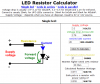
LED Resistor Calculator
Attached are the results of their calculator. 27 ohms.
The calculation they use on their site is:
(Vs - Vf) / (mA / 1000)
so (3.3-2.76) / (20 / 1000)
so 0.54 / 0.002 = 27 ohms
So would the correct way to calculate the current and resistance be?:
"Blue LED
- Source voltage Vs = 3.3 volts
- Forward voltage Vf = 2.76 volts
- Desired current = 20mA (0.02A)
- Calculated resistance required:
-> Vs-Vf = 0.54V
-> Ohm's law is R = V / I
-> R = 0.54 / 0.02
-> R = 27 ohms
- nearest available resistor: 33 ohms
- Calculated actual current (I):
-> Ohm's law is I = V / R
-> I = 0.54 / 33
-> I = 16.36mA
- actual resistor used: 100 ohms
- Calculated actual current (I):
-> Ohm's law is I = V / Ra
-> I = 0.54 / 100
-> I = 5.4mA"
")
 ).
).
